Download
1 / 44
440 likes | 552 Views
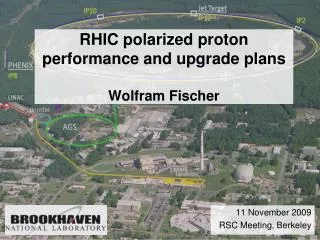
Polarized H - Source Upgrade for RHIC. A.Zelenski, Brookhaven National Laboratory. SPIN 2010, September 28, 2010, Julich. RHIC: the “Polarized” Collider. Polarization facilities at RHIC. Design goal: P= 70 %, L max = 1.6 10 32 s -1 cm -2 50 < √ s < 500 GeV.

E N D
Polarized H- Source Upgrade for RHIC A.Zelenski, Brookhaven National Laboratory SPIN 2010, September 28, 2010, Julich
RHIC: the “Polarized” Collider Polarization facilities at RHIC. Design goal: P=70%, L max = 1.6 1032 s-1cm-2 50 < √s < 500 GeV RHIC pC “CNI” polarimeters Absolute H-jet polarimeter RHIC PHENIX STAR Siberian Snakes Spin Rotators 5% Snake Pol. H- ion source LINAC AGS, 24GeV AGS pC “CNI” polarimeter 200 MeV polarimeter 20% Snake BOOSTER, 2.5 GeV
Operational Polarized H- Source at RHIC. RHIC OPPIS produces reliably 0.5-1.0mA polarized H- ion current. Polarization at 200 MeV: P = 80-85%. Beam intensity (ion/pulse) routine operation: Source - 1012 H-/pulse Linac - 5∙1011 AGS - 1.5-2.0 ∙ 1011 RHIC - 1.5∙1011 (protons/bunch). A 29.2 GHz ECR-type source is used for primary proton beam generation. The source was originally developed for dc operation. A ten-fold intensity increase was demonstrated in a pulsed operation by using a very high-brightness Fast Atomic Beam Source instead of the ECR proton source .
Polarized beams at RHIC. OPPIS 10∙1011(maximum 40∙1011) polarized H- /pulse. LINAC 5∙1011 polarized H- /pulse at 200 MeV, P=85-90% Booster 2∙1011 protons /pulse at 2.3 GeV AGS 1.7∙1011 p/bunch, P ~65% RHIC ~1.5∙1011 p/bunch, P~60-65% at 100GeV P~41% at 250 GeV
Schematic Layout of the RHIC OPPIS. Cryopumps SCS solenoid SCS -solenoid Rb-cell Probe laser Pumping laser 29.2 GHz ECR proton source Na-jet Ionizer cell Sona-transition
OPPIS upgrade with the Fast Atomic Beam Source. The third- Generation. He – ionizer cell serves as a proton source in the high magnetic field. H+ H+ H- H0 H0 The source produces ~ 5 A ! (peak) proton current at 5.0 keV. ~ 10 mAH- current, P = 85-90%. ~ 300 mA (high-brightness) unpolarized H- ion current.
FABS Schematic layout. Na-jet ionizer Rb-cell
Hydrogen atomic beam ionization efficiency in the He- cell. H0 + He → H+ + He + e 80% 10 keV
Pulsed OPPIS with the atomic hydrogen injector at INR, Moscow, 1982-1990. The First-Generation. Atomic H injector Helium ionizer cell ~80% ionization efficiency. H- current 0.4mA, P=65% Lamb-shift polarimeter
Feasibility studies with Atomic Beam Injector at TRIUMF, 1997-99. The Second Generation.
Pulsed OPPIS at TRIUMF, 1997-99. Atomic H Injector. A pulsed H- ion current of a 10 mA was obtained in 1999.
OPPIS upgrade with the Fast Atomic Beam Source.The third generation. He – ionizer cell serves as a proton source in the high magnetic field. F ~140cm H+ H+ H- H0 H0 100 cm
Proton “cannon” of the atomic H injector. The source produced 3 A ! pulsed proton current at 5.0 keV. Ion Optical System with “geometrical focusing”. The source produced 4-5 A ! pulsed proton current at 5.0 keV. ~20 mA H- current, P=80% ~10 mAH- current, P=85-90%. ~ 300 mA unpolarized H- ion current.
The Atomic Hydrogen Injector. Collaboration agreement with BINP, Novosibirsk on polarized source upgrade. BINP physicists are doing the simulations and are involved in the experiments at the FABS test-bench. • Contract with BINP, Novosibirsk. Delivery: January, 2011. • Two sets of sources and power supplies, local control system. • 4- sets of spherical extraction grids (focal length ~150 cm) for polarized source. • 2- sets of shorter focal length (~ 50cm) grids for studies of basic limitation of high-brightness H- ion beam production in the charge-exchange process. • Vacuum system upgrade with TMP for He-cell pumping.
BINP design for the “Atomic Beam Injector”. Plasmatron 4-grid proton extraction system H2 Neutralization cell
BINP design for the “Atomic Beam Injector”. Plasmatron 4-grid proton extraction system H2 Neutralization cell
Ratio of the target current to the emitter current vs focal distance. 5A, H+ → 200mA, H0→ 16 mA, H- Fig. 8. Ratio of the target current to the emitter current vs focal distance: 1 – without magnetic field, 2 – with magnetic field.
Magnetic field maps for Oxford Instr. and Toshiba solenoids. Toshiba solenoid Oxford solenoid Correction coil Rb-cell RF-power input ECR-grids Z- Bz -field component at the solenoid axis. Sona-transition
A new superconducting solenoid. • Contract with Cryomagnetics, Tennesi. • Delivery: April, 2011. • Higher 30 kG field. Better field shape. Cold iron yoke. • He- re-condenser, low maintenance cost. • Two mode of operations. Atomic beam mode –long flattop. • ECR- mode provides field shape for the conventional ECR-mode operation.
Depolarization caused by spin-orbital (LS) interaction in excited 2P states. ~92% at 20 kG –low limit Most of the H aoms are produced in excited n=2 states. A high magnetic field has to be Applied in the optically-pumped vapor cell to avoid depolarization due to spin-orbital interaction.
A new superconducting solenoid. Atomic Beam –mode. ~70 cm flattop Contract with Cryomagnetics, Tennesi. Delivery: April, 2011
Small diameter beam in the FABS. • Atomic H injector produces an order of magnitude higher brightness beam. A 5-10 mA H- ion current can be obtained with the smaller, (about 15 mm in diameter) beam. • Higher Sona-transition efficiency for the smaller beam radius. • Smaller beam emittance : ε ~ B × R 2 • High-brightness source (FABS) will deliver at least 10 times more beam intensity then ECR-proton source within the small ionizer aperture.
97.5% x x x After Sona-transition upgrade, Run 07 Simulations and field measurements. A new diam. 4.0” Sona-shield A new Correction Coil Optimized positions for shield and CC x
Polarization vs. ionizer solenoid current with the 12mm collimator. Maximum polarization from the correction coil scans, collim. -12 mm. 160 A ↔1.16 kG, 81.6%, (95.9%) 200 A ↔1.45 kG, 84.9%, (97.0%) 250 A ↔1.81 kG , 88.1%, (98.1%) Expected: Expected 23 mm collimator. 200 A ↔1.45 kG, 82.5% (97.0%) 250 A ↔1.81 kG , 84.5% (98.1%) A new ionizer solenoid: 250 A ↔1.98 kG , 90.0% (98.4%)
Sodium-jet ionizer cell. Reservoir– operational temperature. Tres. ~500оС. Nozzle – Tn ~500оС. Collector- Na-vapor condensation: Tcoll.~120оС Trap- return line. T ~120 – 180оС. Transversal vapor flow in the N-jet cell. Reduces sodium vapor losses for 3-4 orders of magnitude, which allow the cell aperture increase up to 3.0 cm . Nozzle 500deg.C Collector ~150 deg.C NL ~2·1015 atoms/cm2 L ~ 2-3 cm Reservoir ~500 deg.C
H- beam acceleration to 35 keV at the exit of Na-jet ionizer cell. H- 35 keV Na-jet cell is isolated and biased to – 32 keV. The H- beam is accelerated in a two-stage acceleration system. -32 kV -28 keV -15 keV
H- beam acceleration to 35 keV at the exit of Na-jet ionizer cell. H- 35 keV Na-jet cell is isolated and biased to – 32 keV. The H- beam is accelerated in a two-stage acceleration system. -32 kV -28 keV -15 keV
Hydrogen atomic beam ionization efficiency in the He- cell. H0 + He → H+ + He + e 80% 10 keV
Residual unpolarized H0 beam component suppression by the energy separation. Deceleration H0 + He → H+ + He + e Rb -cell He-ionizer cell H0(10keV) H+(60%) H0(3.0keV) H0(40%) H0(10.0keV) -7.1 kV -7.0 kV -7.0 kV -7.1 kV
Polarization dilution in the FABS. H+ (10keV) H2-cell 0.8% 40% 2% 95% H0(10keV) H-(10keV) H-(42keV) H0 (10keV) He-cell 60% H+ (10keV) Deceleration, ΔE = - 7.0 keV Beam loss at deceleration? ? H+ (3.0keV) 50% H0 (3.0keV) 8.5% H- (3.0keV) 0.8/2.7 =0.3- polarization dilution. 7.0 keV energy separation would allow dilution reduction to less than 0.1%. Acceleration, - 32 keV H- (35keV) 2.7%
Polarization dilution by H2+ in the FABS. ~10% H+2(10keV) H2-cell 0.12% 20% 6% H0(5.0keV) H-(5.0keV) H-(37keV) H0 (5.0keV) He-cell 80% H+ (5.0keV) Deceleration, ΔE=7.0 keV H+ (3.0keV) 50% H0 (3.0keV) 8.5% H- (3.0keV) 0.12/3.0 =0.04- polarization dilution. 2.0 keV energy separation reduces dilution to less than 0.4% H- (35.0keV) Acceleration, 32 keV 3%
LEBT upgrades for the Run 2010-11. A new Spin Rotator Solenoid “Tandem” Einzel Lens New stirrers, Buncher, (Quads?)
Molecular component suppression by the double Einzel lens in the LEBT. Deepak simulations.
Molecular component suppression by the double Einzel lens in the LEBT. Tk 9, current, 200 MeV 32.2 +2.8 =35.0 keV ~10-15% beam intensity losses 1.4 kV 2.0 kV Extractor Voltage, kV
Primary proton beam energy (~10.0 keV) choice. • Higher energy gives higher beam intensity. • Lower ionization efficiency in the He-cell (~60%). • Larger deceleration (~7.0 keV) after the He-cell is required. • H- yield reduction for 10 keV residual unpolarized H0. • Higher energy increases the energy separation efficiency. • At least 10 keV energy is required for molecular H2+ beam component suppression.
OPPIS upgrade with the “Fast Atomic Hydrogen Source” Higher polarization is expected with the fast atomic beam source due to: a) elimination of neutralization in residual hydrogen; b) better Sona-transition efficiency for the smaller ~ 1.5 cm diameter beam; c) use of higher ionizer field (up to 3.0 kG), while still keeping the beam emittance below 2.0 π mm∙mrad, due to the smaller beam diameter. All these factors combined will further increase polarization in the pulsed OPPIS to: -over 85% and the source intensity to 5-10 mA. The ECR-source replacement with an atomic hydrogen injector will provide the high intensity and high polarization beam for polarized RHIC luminosity upgrade and for future eRHIC facilities.
Depolarization factors in the OPPIS. Total: 0.81-0.95 (0.9/0.8)4 ~1.6
A new FABS test bench. TMP for He pumping
FABS operation. Beam energy, 7.0 keV H- current, 12 mA Arc current, 650A
H- ion beam current vs beam energy (within 25 mm ionizer acceptance). H0-intensity H- current, (× 10)
Summary. • Atomic H injector produces an order of magnitude higher brightness beam. • A 5-10 mA H- ion current can be obtained with the smaller, (about 15 mm in diameter) beam. • This reduces polarization losses and produce smaller emittance polarized beam. Neutralization in the residual gas is much smaller too. • All these factors combined will increase polarization to over 85%. Shedule: The new solenoid can be used for the ECR-mode operation in 2012 Run. Completion for 2013 Run.