Download

1 / 38
380 likes | 540 Views
RHIC polarized source upgrade. A.Zelenski, BNL. Workshop on high–energy spin physics, IHEP, Protvino, September 1983. Anatoli Zelenski A new polarization technique. Equal intensity for polarized and unpolarized proton beams. Yaroslav Derbenev “Siberian snakes”.

E N D
RHIC polarized source upgrade. A.Zelenski, BNL
Workshop on high–energy spin physics, IHEP, Protvino, September 1983 Anatoli Zelenski A new polarization technique. Equal intensity for polarized and unpolarized proton beams. Yaroslav Derbenev “Siberian snakes”
RHIC: the “Polarized” Collider Polarization facilities at RHIC. Design goal - L max = 1.6 1032 s-1cm-2 50 < √s < 500 GeV RHIC pC “CNI” polarimeters Absolute H-jet polarimeter RHIC PHENIX STAR Siberian Snakes Spin Rotators 5% Snake Pol. H- ion source LINAC AGS, 24GeV AGS pC “CNI” polarimeter 200 MeV polarimeter 20% Snake BOOSTER, 2.5 GeV
Operational Polarized H- Source at RHIC. RHIC OPPIS produces reliably 0.5-1.0mA polarized H- ion current. Polarization at 200 MeV: P = 80%. Beam intensity (ion/pulse) routine operation: Source - 1012 H-/pulse Linac - 5∙1011 AGS - 1.5-2.0 ∙ 1011 RHIC - 1.5∙1011 (protons/bunch). A 29.2 GHz ECR-type source is used for primary proton beam generation. The source was originally developed for dc operation. A ten-fold intensity increase was demonstrated in a pulsed operation by using a very high-brightness Fast Atomic Beam Source instead of the ECR proton source .
SPIN -TRANSFER POLARIZATION IN PROTON-Rb COLLISIONS. Laser-795 nm Optical pumping Rb: NL(Rb) ~1014 cm-2 Na-jet ionizer cell: NL(Na)~ 3•1015 cm-2 Rb+ Rb+ Proton source H+ H+ Sona transition Ionizer cell H- 1.5 kG field Charge-exchange collisions:~10-14 cm2 Electron to proton polarization transfer ECR-29 GHz Н+source Supperconducting solenoid 25 кГс Laser beam is a primary source of angular momentum: 10 W (795 nm) 4•1019 h/sec 2 A, H0equivalent intensity.
Schematic layout of the RHIC OPPIS. Cryopumps SCS solenoid SCS -solenoid Rb-cell Probe laser Pumping laser 29.2 GHz ECR proton source Na-jet Ionizer cell Sona-transition
Pulsed OPPIS with the atomic hydrogen injector at INR, Moscow, 1982-1990. First generation. Atomic H injector Helium ionizer cell ~80% ionization efficiency. H- current 0.4mA, P=65% Lamb-shift polarimeter
Pulsed OPPIS at TRIUMF, 1997-99. Second generation. Atomic H Injector. A pulsed H- ion current of a 10 mA was obtained in 1999.
OPPIS with atomic H injector layout. RHIC 2012. The third generation.
OPPIS with atomic H injector layout. TMP1 CP1 Neutralizer cell Na-jet cell Atomic H injector He-ionizer cell Rb-cell He Rb Na H2 H+ H0 H- H+ H0
Hydrogen atomic beam ionization efficiency in the He- cell. H0 + He → H+ + He + e 80% 10 keV
H- yield vs beam energy ~ 8.4 % at 3.0 keV beam energy
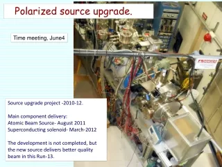
A result of this “upgrade” is practically a new source. • A new superconducting solenoid. • A new atomic hydrogen injector. • A new vacuum system. • A new H-ionizer cell, energy separation system and pulsed PS system. • A new control and interlock system. • Major upgrades of laser system. • Major modifications of the Low Energy Beam Transport system. • Major upgrades in 200 MeV polarimeter. • A new test-bench for atomic injector studies. • Many other upgrades…
“Fast Atomic Beam Source”, BINP 2011 Plasmatron 4-grid proton extraction system ~ 3.5 A equivalent H0 beam H2 Neutralization cell FABS produces 200-300 mA equivalent H0 beam intensity Within the Na-jet ionizer acceptance.
OPPIS magnetic field, Sona-transition field shape control. Internal Correction Coils Large Correction Coil Sona transition Ionizer solenoid Superconducting Solenoid
Atomic Beam Mode, flattop. 65 cm flattop 30 kG
He-ionizer cell and three-grid energy separation system. 3-grid beam deceleration system He-pulsed valve
Sodium-jet ionizer cell Reservoir– operational temperature. Tres. ~500оС. Nozzle – Tn ~500оС. Collector- Na-vapor condensation: Tcoll.~120оС Trap- return line. T ~120 – 180оС. Transversal vapor flow in the N-jet cell. Reduces sodium vapor losses for 3-4 orders of magnitude, which allow the cell aperture increase up to 3.0 cm . Nozzle 500deg.C Collector ~150 deg.C NL ~2·1015 atoms/cm2 L ~ 2-3 cm Reservoir ~500 deg.C
H- beam acceleration to 35 keV at the exit of Na-jet ionizer cell H- 35 keV Na-jet cell is isolated and biased to – 32 keV. The H- beam is accelerated in a two-stage acceleration system. -32 kV -28 keV -15 keV
H- beam acceleration to 35 keV at the exit of Na-jet ionizer cell H- 35 keV Na-jet cell is isolated and biased to – 32 keV. The H- beam is accelerated in a two-stage acceleration system. -32 kV -28 keV -15 keV
New PLC interlock and monitoring system. Graphics by Yuri Bezpalko
H- ion beam current pulse -560 uA at 200 MeV, Rb-96 deg, May 3, 2013 H- ion beam current-700 uA at injection to RFQ
Polarized injector, 200 MeV linac and injection lines. Polarization direction is adjusted vertically in the 750 keV beamline by the solenoidal spin -rotator. 200 MeV polarimeter OPPIS
Source intensity and polarization. • Reliable long-term ∙operation of the source was demonstrated. • Very high suppression of un-polarized beam component was demonstrated. • Small beam emittance (after collimation for energy separation) and high transmission to 200 MeV.
H- beam current and polarization at 200 MeV vs. Rb vapor thickness Polarization in 200 MeV polarimeter H- current (uA) Rb-vapor thickness –nL ( × 1013 atoms/cm2)
Polarization (at 200 MeV) vs. Superconducting Solenoid magnetic field in He and Rb-cells. Magnetic field in Rb-cell, kG
Depolarization caused by spin-orbital (LS) interaction in excited 2P states. ~92% at 20 kG –low limit Most of the H aoms are produced in excited n=2 states. A high magnetic field has to be Applied in the optically-pumped vapor cell to avoid depolarization due to spin-orbital interaction.
Polarization measurements at 255 GeV in H-jet polarimeter, Run-2013, April-25-30
Rb-81, T9-current-295 uA, (Booster input-4.9×10¹¹) 84.2+/-0.5% 83.9+/0.9%
Depolarization factors P = EH2 ∙ PRb∙ S ∙ BRG∙ ELS∙ EES ∙ ESona∙ Eion ~ 85-90% G.Atoian Total: 0.85 - 0.90 G.Atoian 32 9/12/2013
RHIC Polarized beam in Run 2012 OPPIS 0.6mA x 300us→11∙1011 polarized H- /pulse. LINAC (6.0-6.5) ∙1011 polarized H- /pulse at 200 MeV Booster (2.2-2.4) ∙1011 protons /pulse at 2.3 GeV (2.0-2.2) ∙1011 p/bunch AGS RHIC ~1.8∙1011 p/bunch, P~60-65% at 100 GeV P ~ 56% at 250 GeV
Summary • The new source is working. Reliable long-term operation at steady current and polarization. • The maintenance time is significantly reduced. • Polarization is 80-84%, which is 3-5% higher then ECR-based source. It is expected that polarization can be further improved to over 85%. • The source intensity is about 3-5 mA. Due to strong space-charge effects only fraction of this current is transported and accelerated in RFQ and Linac. These losses can be reduced.
Optical pumping of Rb-85 (72.7%), Rb-87(27.8%) natural mixture.. Effective width of Rb 85-87 natural mixture including hyperfine Splitting and Doppler broadening is ~ 3.2 GHz Δν ~ 8 GHz
Reference polarization measurements in AGS for RHIC fills.Beam intensity ~ 2*10^11 200 MeV polarization 70% Fixed target measurements: Pf. <P> = Pf / √(1 +R) ~ Pf (1- ½ Rh) Pf-fixed target measurement RHIC fill # illNumber = 17417, sourcePol_run_fy13 = 82.5573 fillNumber = 17417, agsPolT1_run_fy13 = 71.3816