Download
1 / 42
420 likes | 549 Views
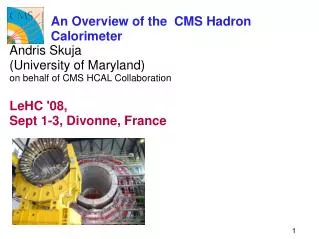
CMS Hadron Calorimeter. Andris Skuja Lv.2 HCAL Project Manager’s Overview US CMS Annual Meeting Riverside, California May 19, 2001. System Overview. HCAL: US does all of HB and optical cables, transducers, front end and readout electronics for HO, HE and HF. HO. HB. HF. HE.

E N D
CMS Hadron Calorimeter • Andris Skuja • Lv.2 HCAL Project Manager’s Overview • US CMS Annual Meeting • Riverside, California • May 19, 2001
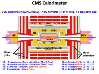
System Overview • HCAL: US does all of HB and optical cables, transducers, front end and readout electronics for HO, HE and HF. HO HB HF HE
US HCAL Responsibilities • The US construction responsibilities for all HCAL subdetectors are well defined: • HB: absorber, megatile production (optics), optical cables & connectors, readout boxes, photodetectors (HPD’s), front end electronics, trigger/DAQ electronics, power supplies, controls: US CMS • HE brass (75%) & scintillator acquisition (only): US CMS • HE optical cables (materials) & connectors, readout boxes, photodetectors (HPD’s), front end electronics, trigger/DAQ electronics, power supplies, controls: US CMS • HO readout boxes, photodetectors, front end electronics, trigger/DAQ electronics, power supplies, controls: US CMS • HF and HF shielding mechanical design: US CMS • HF quartz fiber (Plastic cladding): US CMS • HF readout boxes, photomultipliers, front end electronics, trigger/DAQ electronics, power supplies, controls: US CMS
Non-US Responsibilities • Responsibilities of CMS collaborators • HE: absorber manufacture, megatile production (optics) : R/DMS • HO installation brackets & tooling, megatiles (including scintillator), optical cables & connectors: India • HF absorber manufacture and installation tooling: Russia • HF shielding, support structure: CERN, Russia, Turkey, Iran • HF quartz fiber installation: Hungary • HB/HE/HF: HV Supply Engineering: Bulgaria
Absorber & Tooling • The HB Absorber Team is headed by Jim Freeman • Two HB prototype wedges (PPP1 and PPP2) have been manufactured and delivered to CERN. • All HB- wedges are complete and their assembly tested. Twelve HB+ wedges are finished and six more are in the final machining phase. All 18 HB+ wedges await final test assembly at Felguera in June/July 2001. • All HB Installation Tooling is close to being finished at Felguera of Spain. • The chief mechanical engineer for the design and fabrication of the absorber and installation tooling is Igor Churin (FNAL). He is aided by 3 Guest Engineers (Yuri Orlov, Valeri Polubotko and Vladimir Siderov). • Igor Churin will oversee the HB- and HB+ assembly at CERN (2 months in 2001 and 2 months in 2002).
HB- Absorber HB- absorber is complete. It passed all QC tests and has been disassembled and shipped to CERN.
HB- at CERN HB- wedges and scintillator crates in Bldg 186 at CERN. Scintillators will be installed into wedges in June.
Interior of cryostat Rail support Interior of vacuum vessel for superconducting magnet. The HBs rest on the rail.
HB+ 12 of 18 HB+ Wedges are complete Cradle and tooling ready HB+ will be complete by end of July, ahead of schedule
HCAL Tooling • Completed: Cradles, spiders, lifting fixture, support beams • Left to do: Tie rods, stabilizer Cable block stabilizer Tie rods Spider Cradle Riser Support Beam
The Optical System • The HB megatiles are being fabricated at FNAL in Labs 5 & 8 • Pawel de Barbaro (Rochester) has overall production responsibility for the optical system Readout Fiber (Pigtail) Assembly in Lab 5 is supervised by Howard Budd (Rochester). • The lead technical personnel are Jim Blomquist, Todd Nebel and Ewa Skup. The 14 full time production personnel include Russian (2) and Chinese (2) visitors allowing for quality control transfer to our colleagues abroad. • PPP1 & PPP2 megatiles have been delivered to CERN. More than 80% of the megatiles for HB- and HB+ are finished and many have been shipped to CERN as well. We are on schedule for megatile production being finished in September of 2001. • Optical cable is being manufactured by UIC (Mark Adams). This task will be finished in June of ‘01.
Megatile design, top view Components are the machined scintillator plates, cover plates, fiber assembly (WLS spliced to clear fiber, optical connector) pigtails
Readout Boxes (RBX’s) • US CMS is responsible for the Readout Boxes (RBX’s) for all HCAL subsystems (HB,HO,HE,HF) . • The light signals from the scintillator tile layers are summed optically in the Boxes to form Calorimeter towers. • A new design now exists for HB and HE RBX’s that is modular and can co-exist with the services surrounding HE and HB. The box shell contains a backplane and a cooling circuit. HPD RM’s (Readout Modules) containing a 19-channel or a 73-channel HPD and its corresponding ODU (Optical Decoder Unit) are plugged into the box. It also contains a Calibration Unit and a Clock & Control Module (CCM) as well as HV/LV plug-ins. • Randy Ruchti of Notre Dame is leading the design and fabrication team of this complex item. At Notre Dame he is assisted by Barry Baumbaugh (EE) and Jeffrey Marchant. Jim Reidy is leading the Mississippi effort to fabricate HE Box shells. Mark Adams and the UIC group are fabricating optical “pigtails” for the ODU’s.
HB RBX Full RBX with 19 ch RMs RBX Interior -- HV distributor and backplane
Optical Sorter Interface Card HPD Mount HV Electronics cards RBX Readout Module • The readout module (RM) integrates the HPD, front end electronics, and digital optical drivers.
Photodetectors • The photodetectors for the optical readout of HB, HE and HO are DEP Hybrid Photodetectors (HPD’s) with either 19 or 73 pixel readout. They reside in the Readout Boxes, aligned with the 4T magnetic field. The H1 signals are directed to the 73 pixel HPD’s, while the H2 signals are routed to the 19 pixel HPD’s. Towers with multiple readouts may be processed by either tube type. We are studying the necessity of an independent H1 readout. Eliminating it could realize savings of about $1 million and add time contingency to the project. • Prisca Cushman of Minnesota is responsible for the HPD procurement , characterization and testing. She is assisted by electronics/optical engineer Arjan Heering. • Sergey Los & Anatoly Ronzhin of Fermilab have measured the HPD response at high frequencies. High Frequency cross-talk was observed in ‘99 as were a number of HV problems. These have been solved, one step taken being the aluminization of the diodes. This step contributed to optical cross talk (real photon back scattering) which had to be reduced by 1/4 wavelength coating. We have discovered no new problems and pre-production prototypes will be ready by Fall ‘01.
73 x 2.75mm 19 x 5.5mm The Hybrid Photodiode Tube Fabrication byDelft Electronic Products (Netherlands)Subcontracts:Canberra (Belgium) 22%for diodesSchott Glass (USA) 8% for fiber optic windows Kyocera (Japan) 4%for vacuum feedthru/ceramic carrier CMS Design • 12 kV across 3.5 mm gap with Vth < 3 kV => Gain of 2500 • Silicon PIN diode array, T-type • Thin (200 mm) with 100 V reverse bias for fast charge (holes) collection
Test Confirms Reflected Light Light injected thru fiber APD views reflected light Light Re-emitted photoelectrons photoelectrons pe backscatter
HCAL Electronics • The HCAL Electronics is divided into Front End Electronics (residing in the RBX’s) and the Trigger/DAQ interface electronics (HCAL TRIDAS). The HV/LV support systems as well as the monitoring system complete the electronics system. • John Elias of FNAL is the overall coordinator for this entire hardware subsystem. • The Front End electronics design is supervised by Elias and Terri Shaw (EE) of FNAL. A number of FNAL ASIC designers complete the team. • The TRIDAS project is supervised by Drew Baden of Maryland. The Maryland EE team includes Rob Bard and Tullio Grassi. BU is a major contributor to the TRIDAS project (Jim Rohlf and Eric Hazen (EE)) . Mark Adams of UIC rounds out the design effort. Chris Tully of Princeton is working on the VME readout chain. • The HV system is the responsibility of Fermilab (Anatoly Ronzhin and Sergey Los). The PS’s are being manufactured in Sofia, Bulgaria. • The LV system is the responsibility of FNAL (Claudio Rivetta) • The monitoring task is supervised by John Elias, but consists of many contributors from a number of institutions.
Front End Electronics • The Front End Electronics design and fabrication is an FNAL project. John Elias is the overall manager and coordinator of the electronics project. Theresa (Terri) Shaw (EE at FNAL) is the electronics integration engineer. The FNAL micro-electronics group is leading the front-end electronics ASIC design effort (supervised by Ray Yarema). • The front end electronics design now consists of a modified KTeV QIE chip with an on-board flash ADC on the same ASIC followed by a Channel Control ASIC (CCA). Sergey Los and Alan Baumbaugh (EE’s) act as interface engineers. • The digitized output signals are transmitted over optical links to the CMS Counting Room. Three (or two) ADC channels per link will be transmitted over the CMS rad-hard CERN solution to the counting house. • The ASIC project no longer defines our CRITICAL PATH. We expect to complete these ASICs by August of 2002.
Calibration System • The Calibration system consists of: • Radioactive source system (primary and absolute calibration of all megatiles) • Laser system (stability monitoring and timing system for all megatiles) • LED’s (stand alone system) • QA/QC stations have also been manufactured to ensure megatile uniformity (FSU: megatile scanner; Notre Dame: Pigtail scanner) • Vasken Hagopian of Florida State is the overall manager of all calibration systems. He is directly responsible for the laser system (aided by Kurtis Johnson). • Virgil Barnes and Alvin Laasanen are responsible for the implementation of the radioactive source system. They are responsible for a similar system on CDF. • Yasar Onel is responsible for the implementation of the LED system. • All calibration systems could be finished by end of ‘01 for installation at CERN on time and on budget.
HB Calib Box PPP2 • CERN Bldg 186 Calibration Box #2 prototype P2
HCAL SOURCE CALIBRATION • Schematic layout of HB Air-Motor Source Driver • Envelope is 410 mm x 700 mm
HCAL SOURCE CALIBRATION • Schematic layout of HE Air-Motor Source Driver in the RBX “notch”. Design drawing by A. Surkov Indexer Reel
Trigger/DAQ Electronics • The HCAL Trigger/DAQ electronics serves as an interface between the HCAL raw data and the CMS Level I and Level II trigger electronics or computers. The design is based on modern FPGA’s (leading to future and present flexibility). • Drew Baden of Maryland is the manager for this task. Recently he has been joined by Jim Rohlf (of BU), who is assisting with oversight of these many distributed tasks that constitute this subsystem. The engineering design and electronics manufacture has been divided between Maryland Boston and UIC (HCAL Trigger Card (HTR): Maryland; Data Concentrator Card (DCC): Boston; and the HCAL Readout Controller (HRC): UIC) • The project consists of a Demonstrator phase (2000); a Prototype phase (2001) and a Production phase (2002). The Demonstrator has assumed some of the functionality of the Prototype so that the engineering has overlapped.
Level 1 Trigger Detector Front End Readout Crates Online Controls Event Manager Event Builder Level 2/3 Filter Units Computing Services CMS TriDAS Architecture • Data from CMS FE to T/DAQ Readout Crates • Level 1 “primitives” • Crossing determined • Summing • Tx to Level 1 Trigger • Data is pipelined waiting decision • Level 1 accepts cause • Tx raw data to concentrators • Buffered and wait for DAQ readout • System communication via separate path (TTC) • Clock, resets, errors, L1 accepts…
HCAL Contribution to Trigger/DAQ • Includes: • Receiver cards ( including fiber input receivers and deserializers) • Cables to Level 1 Trigger system • Concentrators • VME crate CPU module • VME crates and racks • Everything between but not including: • Fibers from QIE FEs • DAQ cables Trigger/DAQ Front End Readout Crate - Level 1 Buffer - Level 2 Concentrator - Crate CPU Level 2 and DAQ CMS HCAL HCAL Data QIE Fibers Level 1 Trigger
HTR/Integration@UMD • HTR (Maryland): • 6U Front end emulator and LHC emulator finished • 6U Demonstrator board finished • FE TriDAS Links • R&D on G-Links 800 Mbps finished • R&D on Gigabit Ethernet 1.6 Gbps now beginning • Some work to do to pin down parallel optical links (PAROLI) • Decreases cost from $100 to $50/fiber • Cost and availability concerns • Evaluation of FPGA choices still underway • Functionality: • Understand of FPGA resource requirements • Overall integration • FNAL Aug ’01 source calibration tests • FPGA code very simple – no trigger requirement • Demonstrate • Data receiving, pipeline, synchronization, transmission to DCC • FPGA code development underway shortly • 1 or 2 EE graduate students • Baden
DCC@BU DCC Logic Board TTCRx Xilinx VirtexII XC2V1000 2Mx32 DDRSDRAM S-Link Source Card (optical fibre to DAQ) 3-Channel LVDS Serial Link Receiver (6 used in final DCC) PC-MIP PCI standard • VME Motherboard • Two prototypes working; 5 more boards being built • Link Receiver Board (LRB) • 10 second-generation boards working • DCC Logic Board • PCB Design complete; being fabricated • FPGA coding underway • Test Stand Hardware Complete • Pentium/Linux computer, TTC System Working • Link Transmitters • S-Link cards available Companion LVDS Serial Link Transmitter (for testing only)
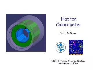
Forward Calorimeter (HF) • The forward calorimeter (HF) is essential for Missing Energy determination as well as for tagging Higgs production • HF is also an optical device, but a Cherenkov light device, sitting in a very high radiation environment. The Cherenkov light is produced and transmitted via quartz fibers to photomulitpliers. The entire electronics and calibration chain for HF is similar/identical to that of HB. • Nural Akchurin of the Texas Tech is the Technical Coordinator of the HF system. HF University groups contribute to the design and manufacture of specific HF subsystems: Larry Sulak, Jim Rohlf & Eric Hazen of Boston University (electronics); Walter Anderson of Iowa State, Yasar Onel of Iowa and Dave Winn of Fairfield (photomultipliers); John Hauptman of Iowa State (HV); Nural Akchurin of TTU (fiber testing and source calibration); Marc Baarmand of FIT (laser calibration); Greg Snow of Nebraska and Richard Wigmans of TTU (luminosity monitoring).
End Plug (FNAL - Design) USCMS Responsibility Matrix Front End, Trig/DAQ (FNAL, BU) DCS , Voltage (FNAL) Backplane matrix (TTU) • Calibration • (Iowa - LED) • (FSU - Laser) • (TTU + PU - Source) Optics and Fibers (TTU, Iowa - QP) Absorber (FNAL-Design) Luminosity (Nebraska, TTU) Photodetectors (Iowa, TTU) Base + HV Design (ISU, TTU) Readout Boxes (TTU) Transporter (FNAL - Design)
HF Wedge and Detector • HF 20-degree sectors will be assembled into a superstructure with the aid of two L-shaped lifting fixtures. Each sector is optically and electronically independent. The design and assembly concepts are developed at FNAL.
Optics: Fiber Routing and Termination • Preliminary fiber insertion studies have been carried out with the PPP2 wedge in Bat186. The optical assembly procedures and quality control process are being worked out by the US and the Hungarian colleagues from KFKI-Budapest. Fibers Source Tubes Wedge Ferrules
Summary and Conclusions • HCAL is 60% finished • Remaining US tasks are readout and trigger electronics related • We have an aggressive schedule to complete by the magnet installation in early 2004, but we believe we can accomplish all our tasks