Download
1 / 40
410 likes | 618 Views
Overview of CMS central Hadron Calorimeter. Sudhakar Katta Tata Institute, Mumbai CMS Collaboration. OUTLINE. Introduction Hadron calorimeter Design aspects Status of sub detectors HB, HE, HO Readout Boxes Calibration tools Conclusions. CMS Detector. HCAL.

E N D
Overview of CMS central Hadron Calorimeter • Sudhakar Katta • Tata Institute, Mumbai • CMS Collaboration
OUTLINE • Introduction • Hadron calorimeter • Design aspects • Status of sub detectors HB, HE, HO • Readout Boxes • Calibration tools • Conclusions
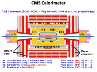
HCAL • HF is covering forward region and status of that is covered by another talk in this conference(Y. Onel). • Central Hadron calorimeter • --- HB || < 1.3 • --- HE 1.3 < || < 3.0 • --- HO || < 1.2 • Tower size 0.087 X 0.087 in X • Sampling Calorimeter • --- brass as absorber • --- scintillator with wls fiber as active medium • HPD is photo device for reading signal • Aim to achieve energy resolution of ~ 100%/E5%
HCAL In HB, HE and HO scint samples -> WLS -> clear -> HPD (in RBX) HO RBX RBX 16 HB 15 HE
Need for HO • In the central region, HB is not thick enough to contain hadronic shower fully, particularly those fluctuated showers which develop deep inside the HCAL. • Need to extend HCAL outside the solenoid magnet and make additional sampling of the shower. • This part outside the magnet coil is referred as Outer Hadron Calorimeter (HO)
HO Location • Geographically located just below the muon system and hence is constrained by the geometry of the muon system.
HO Design Consideration • Basic Detector Elements should map the • barrel hadron Calorimeter ( HB) towers • of granularity 0.087 X 0.087 in h and f. • Should be able to see MIPS. 10 mm thick Bicron BC408 scintillator to be used as the active element. Use 0.94 mm dia WLS Kuraray double clad fibers ( in s shaped grooves), spliced to clear fibers to carry light to HPDs.
Materials • Scintillator • -- HB/HE 4 mm Kuraray SCSN81 • --layer0,layer16 are of thickness 9mm for HB • --first layer of HE is from Kharkov scintillator • -- HO 10 mm Bicron BC408 • WLS Fiber ( HB/HE/HO) • 0.94 mm dia Kuraray Y11 double clad • Clear Fiber ( HB/HE/HO) • 0.94 mm dia Kuraray double clad clear fiber • Fiber layout (HB/HE/HO) • Sigma shape key hole type groove ‘ ‘ • Absorber • -- HB/HE Brass (5cm for HB and 8cm for HE) • -- HO coil and Vac tank, TC iron (30cm)
HB details • HB geometry • total depth ~ 6 • absorber is 5cm thick brass • 18 wedges in each of two half barrels • each wedge covers 20° in • each wedge has 3 megatiles (4x5° in ) • length of megatile 3.7m to 4.3m • 17 layers of megatiles (layer0 to layer16) • fibers brought to edge of tray to a connector • total number of tiles 42624 • longitudinal samplings 1 or 2 depending on
HE details • HE geometry • total depth is ~ 10 • absorber is 8cm thick brass • 19 sampling gaps filled with megatiles • 18 sectors each covering 20° in • each sector has 2 megatiles(4x5° in ) • fibers brought to edge of tray to a connector • total number of tiles 27500 • Longitudinal samplings 2 or 3 depends on
HO details • HO geometry • the location is just below the muon rings • we have 6 trays per sector (6x5=30° in ) • we use 4 grooves per tile • we have 5 muon rings –2,-1,0,+1,+2 • ring 0 has additional layer below TC iron • fibers brought to edge of tray to two connectors • RBX will be located on YB1 lower surface • Total number of tiles 2736 • Longitudinal samplings 1
HB/HE/HO • HB • Absorber wedges made at Felguera,Spain • Megatiles(optics) made at Fermilab • Assembly done at CERN • HE • Absorber wedges made at MZOR,Minsk,Belarus • Megatiles(optics) made at Protvino • Assembly done at CERN • HO • Trays(optics) made in India • Assembled trays will be sent to CERN
HO Tray Design All the tiles in the same f slice of a ring will be packed as a single mechanical unit called the “tray”. It will cover the entire length of a muon ring along Z. Along F, it will only be one tile wide ( 50)
HO Tray Assembly Tiles in a tray will be covered with tyvek and tedler. Will be sandwiched between two plastic plates of 2mm and 1mm thickness for mechanical stability and ease of handling. 2mm thick plastic cover will have grooves to route the fibers from tiles to edge connector. Additional groove for the source tube
Light Collection Clear fibers spliced to WLS fiber will transport scintillation light to an optical connector located at the edge of the tray.
Megatile design, top view Components are the machined scintillator plates, cover plates, fiber assembly (WLS spliced to clear fiber, optical connector) pigtails
±HB MANUFACTURING PROGRESS Preliminary works for the HB assembly foundation 5 wedges of the 2nd set Finished Last wedge of the 2nd set Final machining 6 wedges of the 3rd set Assembled Wedges at Felguera
HB Optics Quality Control Over 20,000 scintillator tiles built and measured RMS of fibers = 4.4% RMS of tiles = 6.5% RMS of wire/coll = 1.2% RMS of average layer light yield = 4.6%
HB – Mechanics and Optics HB- is installed in SX5, HB+ is complete and wedges are stuffed with megatiles in 186. The repairs of the damaged wedge are completed.
Protvino - Pig Tail QC RMS of the light yield transmission is less than 5%.
Megatile Manufacture -HE 10 megatiles/day at Protvino
RBX Readout Module • The readout module (RM) integrates the HPD, front end electronics, and digital optical drivers. Optical Sorter ODU InterfaceCard HPD Mount HV Electronics cards
RBX Status • HB RBX in production (Mississippi). Should be complete by April 02. • ODU’s for HB complete (Notre Dame) 2-3% rms. • HE RBX in design. Design should be complete by April 02 • Production of HE RBXs late spring • HE ODUs to be built in ND factory in summer. • Design HO RBX. Build over summer • HO ODUs in fall (ND)
Calibration Tools • E) Test beam • - normalization between • GeV vs. ADC vs. A,B,C,D • - ratios: elec/pion, muon/pion • - before assembly • a few wedges, 2002 • F) Physics events • - mip signal, link to HO • muon • - calo energy scale (e/pi) • charged hadron • - physics energy scale • photon+jet balancing • Z+jet balancing • di-jets balancing • di-jet mass • W->jj in top decay • A) Megatile scanner: • - Co60 gamma source • - each tile: light yield • - during construction • all tiles • B) Moving radio active source: • - Co60 gamma source • - full chain: gain • - during CMS-open (manual) • all tiles • - during off beam time (remote) • tiles in layer 0 & 9, all fibers • C) UV Laser: • - full chain: timing, gain-change • - during off beam time • tiles in layer 0 & 9, all fibers • all RBX • D) Blue LED: • - timing, gain change • - during the off beam time • all RBX
In Situ Calibration • A) 1 photon + 1 jet • - ET Scale over full h range • by photon-jet balancing • Note: • - depend on ECAL Et scale • - sensitive to ISR (& FSR) • B) Z (-> ee, mm) + 1 jet • - ET Scale over full h range • by Z-jet balancing • Note: • - depend on Tracker and/or ECAL • - sensitive to ISR (& FSR)
Radioactive Source Vertical Slice • Exercise a single channel of HCAL readout from scintillator to computer • Radioactive Source • Scintillator • Optical Fiber • HPD • QIE • Digital optical readout • HTR • DCC • Computer • First complete ~40Mhz readout of HCAL Channel • Successful demonstration of radioactive source measurement for calibration.
Conclusions • HCAL absorber and optics making good progress • HB- assembled in Sep01, HB+ will be in Sep02 • HE- absorber is at CERN, HE+ will be in Oct02 • HO in production, will finish by end of this year • HPDs under control • Front end and Higher level electronics progressing • Looking forward to test beams in summer 02 • Install electronics Spring 03 • Vertical Slice Tests in SX5 in 03
The Hadron Calorimeter • HCAL detects jets from quarks and gluons. Neutrinos are inferred from missing Et. A sampling calorimeter made of brass with scintillator and WLS. Readout is by HPD. HF uses quartz and PMT. US does all HB and all transducers and electronics, RDMS does HE absorber and optics, India does HO optics, and HF is done by US,RDMS,CERN,Iran, Hungary and Turkey.
Beam test results HO is the critical element to ensure that CMS calorimetry is everywhere of sufficient depth to insure a good measurement of the jet energy
CMS QIE Status • Testing shows chip fully functional • Noise as a function of input capacitance being studied • Noise of 3000e- rms achieved with soldered coax connections btw HPD and QIE • Goal is to submit production part by April ‘02
QIE under test TTCrx Clock distributor QIE Test Board
Decide on HE ODU by March Working group – Rohlf*, Gavrilov, Ruchti, Kryshkin – HE ODU is critical path. Trigger options for e also.