Download
1 / 40
400 likes | 516 Views
Andris Skuja (University of Maryland) on behalf of CMS HCAL Collaboration LeHC '08, Sept 1-3, Divonne, France. An Overview of the CMS Hadron Calorimeter. CMS Hadron Calorimeter. HF. HO. HB. HE. Constraints. HCAL sits inside the 4Tesla field of CMS

E N D
Andris Skuja (University of Maryland) on behalf of CMS HCAL Collaboration LeHC '08, Sept 1-3, Divonne, France An Overview of the CMS Hadron Calorimeter
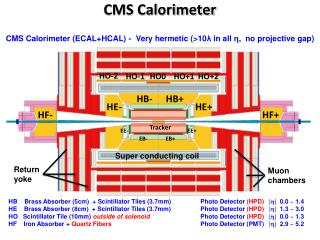
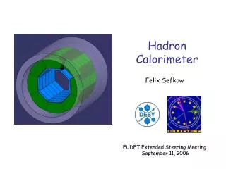
CMS Hadron Calorimeter HF HO HB HE
Constraints • HCAL sits inside the 4Tesla field of CMS • The CMS Crystal EM calorimeter (ECAL) is in front of HCAL • There is a 30cm space between ECAL and HCAL partially filled with dead material • At eta=0 there is less than 6 interaction lengths of HCAL. ECAL provides an additional interaction length • HO embedded inside the MB wheels provides an additional measurement after an additional 2 lambda of material • HB/HE are made out of brass which is non magnetic and denser than iron (adding an additional interaction length inside the field compared to iron)
Had Barrel: HB Had Endcaps:HE Had Forward: HF Had Outer: HO HO HB HE HF HCAL and CMS Section
HCAL response • The HCAL response to hadrons is dominated by the differing e/h for different parts of the calorimeter • For ECAL e/h ~ 3 while for the brass calorimeter itself, the ratio for energies above 10 GeV approaches 1.4. We have measured this ratio as a function of energy and use it to correct the energy response • For eta=o we have to consider a hadron passing through ECAL+HB+HO
HB HE HB and HE Complete in SX5 HF
HF in Bat. 186 The HF were the first Items to be lowered into UX5 Both ends assembled in Bat 186 To move to SX5 July 5 2006 Individual wedges
Calorimeters HB/HO: measure timing, angular direction, hadronic shower energy – calorimetric triggers, jet/met reconstruction. Scintillator tiles are read out with embedded wavelength shifting fibers. brass(non-magnetic absorber) & scintillator tiles. 5.8λI 1.1λI 4T 1 complete EB supermodule (1700 PbWO4 crystals) of width ΔΦ=20o. Crystal length = 25.8X0. Light conversion to signal by 2 APDs / crystal.
HCAL active material and photodetetctors • HB uses scintillator as its active medium. The light is read out by Hybrid Photodetectors (HPDs). Because of the magnetic field we observe scintillator brightening (due to “chemistry” as well as geometry) • The HPDs exhibit intrinsic noise which is maximum in the range of 0.5 to 2.5 Tesla. The HO HPDs are in a field of 0.2 to 0.45 Tesla • The HF is constructed from quartz fiber bundles that only are sensitive to Cherenkov light. They are read out by PMTs which are sensitive to the passage of charged particles through the PMT window
Holding Calib in Field- MTCC #2 HPD pixel cross talk due to electrons backscatter #1 Scintillator brightening 5% up @ 4T 10% up @ 4T No cross talk in B-field e- trapped along B-field line. More light output in B-field
Test Beam and HCAL response Our knowledge of the HCAL response comes from Test Beam. For HB +HO we took test beam data in 2002, 2003, 2004 and 2006. We had the final ECAL supermodule as part of the TB setup in 2006 For HE we took data in 2007 with an EE+SE module in front
Test Beam 2006 Setup • HB: 40 deg in Φ • HE: 20 deg Φ • HO: Ring 0,1,2 • ECAL(SM9): 20 deg in Φ • +final CMS electronics Pivot ~ interaction point
Wire Source Calibration • The response of each HB scintillator tile of each layer measured: 5-mCi Co60 moving wire radioactive source. • Light attenuation in the optical fibers, loss in fiber connectors, and the HPD gain differences. • fiber length increases with η • tower-to-tower calibration precision: 2% --> derived by comparing the consistency of the relative source and beam data. • All tiles were sourced in TB as well as for HB/HE in SX5 Calibration constants for the 4 Φ sectors of HB.
H2 Beam Line at the SPS • Beam cleaning: • Single hit in S1, S2 and S4 trigger counters (S1*S2*S4 define 4x4 cm2 area on the front face of the calorimeter). • Remove wide angle secondaries: Beam Halo counters (BH1-4) 7x7 cm2 hole. (Freon134a) pedestal (CO2) beam direction
Particle ID in the Very Low Energy Mode: • Muons: Muon Counters • Electrons: CK2 and CK3 • Protons: CK3 and Time-of-flight counters (TOF) • Kaons: TOF and CK3 • Pions: All the remaining particles. -- CK3 pressure set depending on the desired discrimination between electrons, pions, and kaons. -- TOF1 & TOF2 separation ~55 m. Δt ~ 300 ps. Protons and pions(& kaons) are well separated up to 7 GeV/c w/ TOF system alone.
Beam Composition • High energy mode • no anti-proton contamination in negative beams. • Beam almost all protons at 350 GeV/c in positive beams. • The beam content depends strongly on the momentum. • At higher momenta the beam is largely pions. • At lower momenta electrons dominate.
Combined Calorimeter (EB+HB+HO) Response HB: 3x3 towers EB: 7x7 crystals HO: 3x2 towers Energy Scale: EB: 50 GeV electron HB: 50 GeV electron At 5 GeV: pion resp. ~62 % proton resp. ~47% antiproton resp. ~70%
Available Energy Eavailable(pions,kaons) ~ KE + m Eavailable(P) ~ KE Eavailable(P) ~ KE + 2mp
π+/π- Response Ratio • Response to π+ > response to π- increasing with decreasing energy → at 2 GeV π+ is 10% greater than π- Charge exchange reactions: π++n →π0+p (1) π-+p →π0+n (2) The heavy nuclei in the calorimeter material has 50% more neutrons than protons -- the effect of reaction 1 is larger than 2.
π-/p Response Ratio • Response to protons is systematically smaller than that of π-
π/p Response Ratio • Larger fraction of baryons start showering in EB since the total cross section for p > π-. • fraction of particles passing through EB without interacting • pions: 41% • produce more π0. Even though fewer π- interact, those that interact have larger signal • protons: 35% • The effective thickness of EB • pions: 0.89λI • protons: 1.05λI
µ Response • Noise in a single tower of HB ~200 MeV • Very good isolated muon identification. • HB trigger electronics is designed to generate an isolated muon trigger. 150 GeV Muons
Optimization of Energy Reconstruction • The response for charged hadrons is not a linear function of energy for non-compensating calorimeters, e/h≠1. • Moreover, EB and HB have very different values of e/h. • Therefore, corrections are needed to obtain the correct mean particle energy. reminder: e/h is the conversion efficiency of em and had energy to an observable signal.
“Bananas” for π Beams MIP in EB e/h = 1 line.
Response Optimization HB Response to π's E(HB) > 8 GeV: π/e=[1+(e/h-1)f0]/(e/h) f0=0.11logEHB (Wigmans) --->e/h=1.4 _________________ E(HB) < 8 GeV: 0.18log(EHB)+0.14 • Apply thresholds: • 7x7 EB crystals < 0.8 GeV • 3x3 HB towers < 1.0 GeV • 3x2 HO towers < 2.0 GeV • <π/e> for HB as a function of <EHB> using MIP in EB events. • Correct HB energy using π/e function • Determine <π/e> for EB as a function of <EEB> using the corrected HB energies and the beam energy constraint. • Correct EB energy using π/e function • Correct the remaining non-linearity as a function of EB energy fraction. w/ events that have significant energy both in EB & HB. EB Response where E*HB= corrected energy = EHB/(π/e)HB <(π/e)EB>=0.057log(EEB)+0.490
Total Response vs EB Fraction 100 GeV π Z=EEB/(EEB+EHB) hadronic shower in EB fluctuates largely to neutrals. So we do the final step of correction as a function of Z.
“Bananas” of the Corrected Barrel System 20 GeV 100 GeV
Corrected Resolution and Response • Linearity restored within 5% for p≥5 GeV and 2-3% for p≥9 GeV. rms/E=a'/√E⊕b' σ/E=a/√E⊕b σ/E = a/√E⊕b = 84%/√E⊕7% in P = 5-300 GeV/c
Hadron Outer Calorimeter for High Energy Particles • Note the reduced low energy leakage tail.
Absolute Response vs pT Barrel: |η|<1.3 30
Abnormal Events in HF PMTs • These events are most likely to be from Cerenkov radiation from particles directly hitting the PMT window. • peak of muon signal ~ 200 GeV • The glass window is plano-convex. • 1mm thick in center • 6.1mm thick at the edges • These events were also seen in TB07
HB/HE HPD Noise • During the 2006 Magnetic Field tests it was observed that the HPDs produced significant noise pulses which were enhanced in intermediate fields. However the rates are low. • The noise is due to ion feedback (from ions formed in the silicon of the HPDs) and from dielectric flashover in the walls of the tubes • If ExB is large this noise significantly reduces the lifetime of the HPDs
Noise Pulse spectrum 13k triggers at 60 fC, threshold 31 HPDs (496 pixels),~, rate ~15Hz B=0T, HV=8kV Regular pedestals, RMS (10bx) = 1.4fC Spectator pixels (below threshold, but in same noisy HPD that triggered event Pixels that triggered event Tail extends above 10k fC (2 TeV) 1GeV=5fC fC 20GeV 40GeV 60GeV 80GeV 100GeV
Noise rates vs threshold for three different HV settings The noise rates from 30 HPDs used in the MTCC is multiplied by a factor of 10 to indicate an overall noise rate for HB/HE (300 HPDs) 8kV data 7kV data 6kV data 100 kHz 10 kHz 1 kHz Single tower threshold, 10 bx sums 100 Hz 10 Hz 10 GeV@6kV 100 fC 80 fC 10 GeV@7kV 10 GeV@8kV 20 GeV 6 GeV
Resolution: (w/ noise)/(w/o noise) Ratio of sigmas from Gauss fit. Overlapped channels: Noise simulated only in eta=2,phi=2 (no noise in other channels) All channels: all channels are assumed to be noisy.
Nb. of Events per 2.0 GeV MET from ttbar+3jets sample Blue: Nominal MET without HPD Noise Red: MET with HPD Noise Example: MET
Photodetector replacement • We have some difficulties both for the central HCAL with HPDs as well as for HF with PMTs • We are actively investigating the replacement of all photodetectors with Silicon PhotoMultipliers (SiPMs) • Many types of SiPMs exist on the market ranging from ones with a few pixel readout to ones with 150,000 pixels • We have investigated • Dynamic range • “Dead time” • Rad Hardness (radiation tests of a large range of neutron energies from thermal to hundreds of MeV • Magnetic field effects (0 to 6 Tesla and different angles)
e/h Corrections and HCAL upgrade • All calorimeter builders know that the knowledge of e/h on an event by an event basis is the answer to better calorimetry • The Dream Calorimeter (scintillating and quartz fibers) • Energy flow and the separation of em clusters from hadronic ones • Any upgrade of the CMS calorimeter cannot change the mechanical structure of the calorimeter, however we can consider changing the readout (better sampling)
Upgrades • The Upgrade timetable has been reset. During the first upgrade period the Luminosity will be increased by a factor of 2 by 2013. This will be achieved by the removal of limiting apertures (in the insertion quads). • A second upgrade period will follow ending in 2017 that may increase the Luminosity be a further factor of 3 or more. The second Lumi increase will be achieved by replacing the PS and increasing the injection current. • The HCAL upgrade will consist of a number of tasks: • SiPM replacement of HPDs and PMTs • HE tile replacement (not necessary until the second upgrade) • HB front end upgrade (optimize number of readouts per HCAL tower and replace ODUs, QIEs, HPDs, etc but leave in place the input and output fibers) • HCAL readout and trigger upgrade • HF upgrade (present HF channels at large eta will die after 10 years of operation at present Luminosity )
Summary & Conclusions • The CMS calorimeter is installed and waiting for beam • The CMS calorimeters have been exposed to particle beams with momenta 2-350 GeV/c. (electrons, muons, pions, kaons, and protons over a substantial energy range) • We now await the LHC start-up for calibration with data • An upgrade of HCAL is under study and has been partially funded