Download
1 / 32
320 likes | 417 Views
CMS Outer Hadron Calorimeter (HO) Project. Naba K Mondal Tata Institute, Mumbai, India. Need for HO. In the central region, HB is not thick enough to contain hadronic shower fully, particularly those fluctuated showers which develop deep inside the HCAL.

E N D
CMS Outer Hadron Calorimeter (HO) Project Naba K Mondal Tata Institute, Mumbai, India
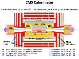
Need for HO • In the central region, HB is not thick enough to contain hadronic shower fully, particularly those fluctuated showers which develop deep inside the HCAL. • Need to extend HCAL outside the solenoid magnet and make additional sampling of the shower. • This part outside the magnet coil is referred as Outer Hadron Calorimeter (HO)
HO Location Geographically located just below the muon system and hence is constrained by the geometry of the muon system.
HO Coverage • HO covers the central rapidity region ( |h| < 1.26) occupied by the five Muon Rings. ( numbered as -2,-1,0,1,2) • For Ring 0, there will be two HO layers ( Layer 0 & 1) on either side of the 18 cm thick tail catcher iron at R=3.82 m and 4.07 m • For Rings -2,-1,1 & 2, there will be a single HO layer ( Layer 1) at R= 4.07 m
Simulation Study • Use CMSIM Version 113 for CMS detector simulation • Use tracker geometry as in post-ECAL pre-Tracker TDR • Use ECAL geometry as in ECAL TDR • Barrel inner hadron calorimeter with 17 layers in front of the coil • HO consists of: • Two layers in ring 0 on either side of the tail catcher iron • One layer in rings 2,1,-1 & -2 • Showers are generated using GEANT for electromagnetic and GHEISHA for hadronic component
Simulation Study Effect of leakage is visible from 70 GeV and increases with energy Effect of leakage is smaller at higher h
Simulation Study Energy resolution: The constant term improves after addition of HO Fraction of events having measured energies 3s below the mean value Leakage is < 1%
1996 Test beam results Energy Resolution Leakage
Simulation Study Effect of HBO on missing energy QCD events
Design Consideration • Basic Detector Elements should map the barrel hadron Calorimeter (HB) towers of granularity 0.087 X 0.087 in h & F • Should be able to see MIPs as it is located at the tail end of the shower. MIP signal is also needed for calibration purposes. 10 mm thick Bicron BC408 scintillator to be used as the active element. Use 0.94 mm dia WLS Kuraray double clad fibers (in s shaped grooves), spliced to clear fibers to carry light to HPDs located on the outer edge of the muon system
HO Tile design • Light from individual tile is collected using WLS fiber. • Fibers are held inside the tile in keyhole type grooves • There will be 4 identical s shaped grooves per tile. • HO has 95 different tile dimensions, 75 for layer 1 and 20 for layer 0. • Total number of tiles -- 2736
HO Tray Design • All the tiles in the same f slice of a ring will be packed as a single mechanical unit called the “tray”. • It will cover the entire length of a muon ring along Z. • Along F, it will only be one tile wide ( 50)
HO Tray Assembly • Tiles in a tray will be covered with tyvek and tedler. • Will be sandwiched between two plastic plates of 2mm and 1mm thickness for mechanical stability and ease of handling. • 2mm thick plastic cover will have grooves to route the fibers from tiles to edge connector. • Additional groove for the source tube
Light collection • Clear fibers spliced to WLS fiber will transport scintillation light to an optical connector located at the edge of the tray.
Optical Cable Routing Optical cables made of 0.94 mm diameter clear fibers carry light from the tray connector to the HPDs located in a Decoder box outside the muon system
Pre Production Prototype Sector Aim: To test a small number of modules using test beam to establish the production procedure and to optimise the detector design: PPP1: Cover 200 in F and one half barrel ( 2 and 1/2 rings) in Z Need: 8 half length Trays ( 1.27 m) for ring 0 8 full length Trays ( 2.54 m) for rings 1 & 2 # of Tiles : 76 # of pigtails : 32 These Trays were exposed to test beams at CERN in the summer of 98 PPP2: Additional 8 trays made and transported to CERN this year to cover one F sector completely for this year’s combined run with HB and HE modules
Test Beam Modules Finished Tray PPP tile with 4 s grooves visible Pigtial with connector
Test Beam Results Response of the HO tiles was measured • With Cosmic ray Muons (with PMTs) at TIFR • With muon beams at CERN • Using HPDs with D0 pre-amplifier electronics • Using HPDs with QIE prototype electronics ( Proof of principle) • Using radioactive wire source • Using X-Y scanner
Pedestal subtracted muon ADC signal from a ring 0 HO tower- (layer 0 and layer 1 combined) Signal = 34.7, sp= 9.4, S/N = 4 Pedestal subtracted muon ADC signal from a ring 1 tile ( Single layer). Signal = 18, sp=10, S/N = 1.8 Test Beam Results
Test Beam Results Fine scan of an HO tile ( Tile # 124) using 2 cm X 2cm beam spot to test tile uniformity
Test Beam Calibration LED data was used for calibration of individual channels.
Photo Electron yield due to MIP For HO tiles, we have estimated p.e. yields using test beam muon spectrum and the LED calibration data Ring 0 Tiles Ring 1 Tiles
Source Calibration HO trays have also been calibrated using wire source scanner as well as X-Y source scanner
HO with QIE + HPD Muons could be seen in HO with the QIE + HPD contained within 2 time slices of 40 MHz.
HO Status • Need for an Outer Hadron Calorimeter (HO) in the barrel region has been established. Simulations and test beam results show that HO will improve the energy resolution and is necessary for physics involving missing Et. • We have a detailed Engineering design for HO. • We have tested Pre-Production Prototype (PPP) Modules with HPD readouts using muon beam at CERN in 1998. Results show that we are sensitive to MIPs which is one of our design goals. • We have also tested these modules using radioactive wire source as well as using X-Y source scan. • Through the exercise of producing the PPP modules, we have developed all the tools and necessary procedures for QC/QA and are ready to enter the production stage.
HO Technical Board Within India-CMS collaboration we have a Technical Board to discuss and decide on various technical issues related to HO. Current Members of the Technical Board: • Naba K Mondal (Coordinator) • Atul Gurtu • M.R.Krishnaswamy • K.Sudhakar • J.B.Singh • R.S.Koppikar • S.N.Ganguli (India-CMS contact person)
HO Task Coordinators • Naba K Mondal : Technical Coordinator • M.R.Krishnaswamy : Incharge of overall Quality Control • J.M.Kohli : Incharge of the Chandigarh Center
Production Responsibilities • Machining of Scintillator tiles will be done at two centers • 25% of tile grooving and the necessary QC will be done at Chandigarh • 75% of tile grooving at Mumbai ( TIFR & BARC) • All the remaining jobs will be done at the Optics Centre, TIFR, Mumbai with participation from Chandigarh group • Procurement of all raw materials ( Scintillator sheets,WLS and Clear fibers, Tyvek and Tedler sheets, plastic sheets, cutters etc) will be done through the mumbai center. • Shipment of all the trays will be done through the Mumbai centre