Download
1 / 49
490 likes | 562 Views
Physics Hall D WBS 1.5. Elton Smith. Independent Project Review of 12 GeV Upgrade Jefferson Lab July 12 – 14, 2005. Introduction to Hall D and the GlueX experiment Scope for 12 GeV Upgrade Cost Overview Implementation Plan R&D plan PED effort Construction Detailed example

E N D
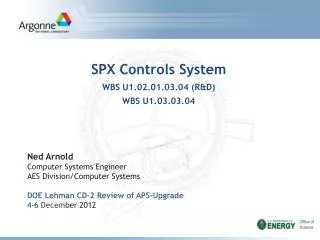
Physics Hall DWBS 1.5 Elton Smith Independent Project Review of 12 GeV Upgrade Jefferson Lab July 12 – 14, 2005
Introduction to Hall D and the GlueX experiment Scope for 12 GeV Upgrade Cost Overview Implementation Plan R&D plan PED effort Construction Detailed example Checkout/Commissioning Schedule Summary Outline
Hall D is a new experimental hall to be located on the east side of the north linac Construction costs for the tunnel and experimental area is the civil estimate Delivery of the electron beam is the responsibility of Accelerator The design, construction and commissioning of the photon beam and experimental equipment is the responsibility of Hall D/GlueX The GlueX physics collaboration (approximately 70 people from 25 institutions) has been together for six years Provides scientific motivation for mapping the spectrum of gluonic excitations Working on R&D projects relevant to the detector design Taking advantage of existing hardware Solenoid magnet used for the LASS experiment at SLAC and the MEGA experiment at LANL Lead glass used in BNL E852 Overview
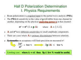
The physics goal of GlueX is to map the spectrum of hybrid mesons starting with those with the unique signature of exotic JPC . • Identifying JPC requires an amplitude analysis which in turn requires • linearly polarized photons • detector with excellent acceptance and resolution • sensitivity to a wide variety of decay modes which include photons and charged particles Hybrid mesons: glue is excited This, coupled with a hybrid mass reach up to 2.5 GeV, requires 9 GeV photons produced using coherent bremsstrahlung from 12 GeV electrons. Physics goals and key features Normal mesons: glue is passive
Tagger area Hall D North linac Electron Beam dump 75 m Photon Beam dump East arc Solenoid- Based detector Electron beam Collimator Experimental Hall D Coherent Bremsstrahlung photon beam Tagger Area Photon beam and experimental area Top View
Incoherent & coherent spectrum 40% polarization in peak tagged (0.1% resolution) Coherent Bremsstrahlung 12 GeV electron beam flux This technique provides requisite energy, flux and polarization photons out collimated electrons in spectrometer (two-magnets) diamond crystal photon energy (GeV)
Hall D Detector Hermetic detection of charged and neutral particles in solenoid magnet Tagger Spectrometer (Upstream)
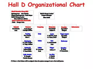
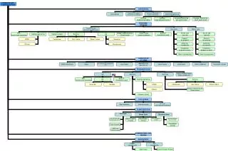
Hall D Organizational Chart Proposal for merging GlueX collaboration with 12-GeV Upgrade Project Organization reflects the WBS outline
Institutional Responsibilities • The GlueX collaboration has designed and optimized the detector to study gluonic excitations. Many university groups have contributed to the R&D and development of major subsystems. • SolenoidJLab • Detectors • TrackingCarnegie Mellon, Ohio U, Florida International U • CalorimetryU of Regina, Florida State, Indiana U, Inst for High Energy Physics (Protvino), U of Athens • PIDIndiana U, Inst for High Energy Physics, U of Tenn, ORNL • ComputingJLab, U of Regina, Indiana U, Carnegie Mellon, U Connecticut, Christopher Newport U • Electronics Indiana U, JLab, U of Alberta, Indiana U Cyclotron • BeamlineCatholic U of America, Glasgow U, U of Connecticut • InfrastructureJLab
Facilities in place Assembly facilities at JLab in Test and Experimental Equipment Labs University facilities already in use to build large scale prototypes (e.g. barrel calorimeter, time-of-flight counters, and central drift chamber) Infrastructure for smaller projects available at other universities Procedures and policies in place JLab Readiness Reviews standard for all installations (EH&S Manual Chapter 3120) Hazard Identification Worksheet and subsequently Task Hazard Analysis performed for potential high-risk tasks (EH&S Manual 3210-T2&T3) Established practice of JLab/GlueX reviews (Electronics Review 2003, Detector Review 2004, Solenoid Assessment 2004) Trained personnel already at work Refurbishment of solenoid at IUCF is providing a training ground for personnel Existing staff at Indiana University built the original E852 Pb glass calorimeter, and is reconfiguring it for Hall D Full-scale prototyping efforts at universities are developing the infrastructure and training for the construction effort Hall D Status
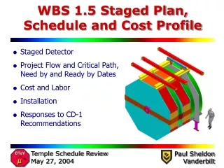
Hall D: Scope • Level 3 WBS Elements • 1.1.5. R&D • 1.9.3 ACD • 1.2.3. PED • Construction • 1.5.1. Solenoid • 1.5.2 Detectors • 1.5.3. Computing • 1.5.4 Electronics • 1.5.5 Beamline • 1.5.6. Infrastructure
Risks No significant technical risk for the base design Potential to mitigate cost and schedule risks from detector elements that are still at the conceptual stage R&D Barrel calorimeter: to study light collection and readout of barrel calorimeter in the magnetic field; test fibers to optimize performance and minimize cost Flash ADC: to develop high-density boards, balance experiment requirements with available clock speed options Cerenkov detector: to advance the conceptual design, verify efficient light collection and detection in the magnetic field Hall D R&D is 21% of the Upgrade Project R&D budget WBS 1.1.3 Hall D R&D
Major cost is in Detectors, followed by Electronics PED is 9% of construction, supplemented by a strong R&D program Total contingency is in line with overall project Contingency on infrastructure reflects the conceptual stage of project for a new hall Hall D Level 4 TEC Elements (FY05 $K Direct)
WBS 1.2.3 Hall D PED Effort • (FY05$K direct) Notes • Solenoid PED effort is part of refurbishment effort • 12-GeV specific portion will be done as a design-build project • Infrastructure • Initially conceived as a design-build project with only global installation drawings. Now realize that more detailed design will be needed and must re-evaluate breakdown between PED and construction
Detectors (WBS 1.2.3.2, $766K) Evenly split between tracking, calorimetry and Particle ID Construction drawings for all detector systems, estimated from previous experience in building similar systems Supplemented by contributed effort at universities Computing (WBS 1.2.3.3, $481K) Investment in online and offline software design leads to savings in the long run Electronics (WBS 1.2.3.4, $683K) Project builds on the developments for the 6-GeV program (e.g. pipeline TDC and Flash ADC) Beamline (WBS 1.2.3.5, $339K) Integration of magnets and vacuum chamber Hall D PED FY05 $k Direct
WBS 1.5.1 Hall D Construction Cost Overview • (FY05$K direct)
HALL D COST METHODOLOGY • Costs are based on: • Quotes from vendors 0% • Catalog price 1% supporting electronics • Estimates from vendors 16% straws, fibers, scint, pmts, TDCs, tagger magnet • Previous JLab experience 51% barrel calorimeter, forward and central drift chambers, DAQ, solenoid, forward calorimeter beam, tagger hodoscope, installation • Information from other labs, 19% forward drift chambers, Universities, etc. upstream photon veto, Cerenkov detector, GRID, trigger • Engineering judgment 13% yokes, FADC, tagger magnet assembly, assembly
TEC costs are for yoke modifications and installation only Yoke modifications are based on Tosca model for solenoid Installation costs are based on experience with disassembly of magnet at Los Alamos and shipment to IUCF for refurbishment Reason 2, 4 SOLENOID: Cost Background (FY05 $K Direct) • Reason • 1. = Catalog • 2. = Engineered • 3. = Designed • 4. = Conceptual Magnet before shipment to IUCF for refurbishment
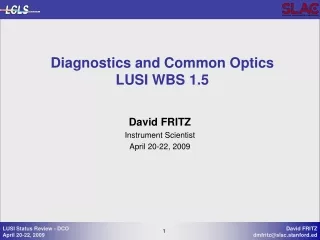
WBS 1.5.2 DETECTORS Tracking Calorimetry Particle Identification
WBS 1.5.2 Hall D Detectors (FY05 $K Direct) Reason 2, 4 2, 3 2, 4 • Reason • 1. = Catalog • 2. = Engineered • 3. = Designed • 4. = Conceptual Pb glass detector used for Brookhaven E852
Tracking Forward DC (WBS 1.5.2.1.1, $1.6M) consists of four superlayers of 6 packages of drift wires and orthogonal cathode planes. Small prototype tested. Central DC (WBS 1.5.2.1.2, $1.4M) is a cylindrical straw tube chamber. One fourth full-scale prototype completed. Hardware costs estimated based on prototypes and number of channels Manpower estimate from previous construction projects and experience with prototypes DETECTOR: Cost Background FY05 $M Direct
Calorimetry Barrel Calorimeter (WBS 1.5.2.2.1, $5.9M): Costs based on budgetary estimates for components and experience with building one full-scale module – More on barrel later… Forward Calorimeter (WBS 1.5.2.2.2, $1.1M): Reconfiguration of E852 Pb glass to Hall D geometry (2300 channels) Upstream Photon Veto (WBS 1.5.2.2.3, $0.4M): estimate based on standard Pb/scintillator detector technology (112 channels) DETECTOR: Cost Background FY05 $M Direct Barrel Pb Glass UPV
Particle Identification Time-of-flight (WBS 1.5.2.3.1, $0.6M) Cost is based on full-scale prototypes built and tested in recent beam test at TRIUMF (168 channels) Cerenkov Detector (WBS 1.5.2.3.2, $0.8M): Conceptual design is costed using previous experience (40 pmts) Note: Additional PID information comes from using barrel calorimeter timing (included in calorimetry) and dE/dx using FDC and CDC (included in tracking) DETECTOR: Cost Background FY05 $K Direct Time-of-flight system axis
(FY05 $K Direct) Reason 1, 2 3 3 WBS 1.5.3 COMPUTING Requirements Level 1 initial rate: 20 kHz @ 107g/s Level 3 rate: 15 kHz to tape Offline Farms: 1 PB/year • Reason • 1. = Catalog • 2. = Engineered • 3. = Designed • 4. = Conceptual
DAQ (WBS 1.5.3.1, $1.2M) 100 single-board crate CPUs Switches and networks Online computer including disk for staging Online computing (WBS 1.5.3.2, $1.4M) 745 m-w including university manpower (approx 2x CLAS) Includes manpower for electronics integration, run management and control, slow controls and monitoring, networking, alarms and interface to online farm Offline computing (WBS 1.5.3.3, $0.3M) Coordinate work at collaborating institutions and resources in Computing Center and GRID activities 477 m-w, mostly using contributed university manpower, which is typically how offline computing is handled COMPUTING: Cost Background FY05 $M Direct
Every event block Trigger Every event Analog Data To ROC Front End “Digitizer” Digital Pipeline FE/DAQ Interface Event Block Buffers WBS 1.5.4 ELECTRONICS Front-ends fully pipelined Pipeline TDC Flash ADC
Reason 4 3 3, 4 1 1, 2 WBS 1.5.4 Electronics (FY05 $K Direct) • Electronics includes crate-based electronics only • On-board detector electronics (pre-amps) and cabling is included in the cost for each detector subsystem • 18,600 channels of Flash ADCs to measure charge • 4,300 channels of Pipeline TDCs to measure time • Reason • 1. = Catalog • 2. = Engineered • 3. = Designed • 4. = Conceptual
Flash ADC (WBS 1.5.4.1, $2.6M) Cost extrapolated from prototypes and engineering design concepts University manpower also available Pipeline TDC (WBS 1.5.4.2, $1.1M) Cost based on 100 boards built for the 6-GeV program Trigger(WBS 1.5.4.3, $0.5M) Previous experience used to estimate conceptual design for custom trigger Crates, racks, HV, auxiliary electronics ($1.5M) ELECTRONICS: Cost Background FY05 $M Direct
Crystal and goniometer 75 m target Active collimator and monitoring Tagger magnets Hodoscope • WBS 1.5.5 Beamline (FY05 $K Direct) Reason 3 2 3 • Reason • 1. = Catalog • 2. = Engineered • 3. = Designed • 4. = Conceptual
Tagger magnet (WBS 1.5.5.1.1, $1.4M) Cost estimate from commercial vendor Integration manpower included to support construction Tagging spectrometer hodoscope (WBS 1.5.5.1.2, $0.6M) Experience with Hall B spectrometer Target and beamline (WBS 1.5.5.2 and 1.5.5.3, $0.9M) Based on experience with similar systems (e.g. g8 experiment in Hall B) Photon beam Two-magnet tagger Vacuum chamber and hodoscope Electron beam BEAMLINE: Cost Background FY05 $M Direct
(FY05 $K Direct) Reason 4 4 3 WBS 1.5.6 Infrastructure • Reason • 1. = Catalog • 2. = Engineered • 3. = Designed • 4. = Conceptual • Assembly (WBS 1.5.6.1, $0.4M) • Detectors inside magnet • Installation (WBS 1.5.6.2, $1.6M) • Extend utilities from building to detectors • Fabricate support structures to hold detectors • Rigging of all detectors into place Technical staff: 440 m-w Contract labor: 550 m-w
Construction cost is $5.9M Composed of 48 modules of scintillating fibers and lead Based on successful KLOE experiment at DAFNE Procurement of fiber is a long-lead item Fabrication of each module takes 1 month Mass is 22 tons Bcal Magnet yoke Detailed Example: Barrel Calorimeter Follow one subsystem with more detail
Module length is 390 cm Module thickness is 25 cm Calorimeter requires 4,000 km of 1 mm scintillating fibers Beam tests conducted at TRIUMF in June, 2005 Base design assumes standard pmts and light guides. R&D program to investigate the possibility of using Silicon PMTs (SiPM) which have low sensitivity to magnetic fields, and test fibers to optimize performance and minimize cost. Detailed Example: Barrel Calorimeter
Detailed Example: Barrel Calorimeter • Estimated student manpower for fabrication was 20 m-w/module • Estimated student manpower for cutting and swaging was 0.5 m-w/module • Machining cost used was $2.8k/module (48 modules needed)
Calorimeter modules will be fabricated at the University of Regina and University of Alberta Module will be machined using the extensive machine shop capabilities at the University of Alberta Completed modules will be shipped to JLab for installation in the solenoid and attachment of photodetectors Detailed Example: Barrel Calorimeter Present planning is based on the following scenario
6 Inch Plate Rollers Ring girder Iron Yoke1 Detailed Example: Barrel Calorimeter Concept for installation of barrel into solenoid guides the proposed schedule Step 1. Coil 1 inserts into the iron yoke1. Six inch Iron plate with the ring girder is bolted to the yoke. Step 2. Similarly all the other 3 iron yokes, coils and ring girders are positioned in place Step 3. Assemble Bcal separately using straps for support. Step 4. Roll Bcal into position.
Summary of construction costs broken down according to labor, expenses and procurement WBS 1.5.1 Construction Cost Break-out (FY05 $K Direct)
Major cost items Barrel calorimeter (Detectors) FADCs (Electronics) Contingency is in line with overall project. It is an average of elements that are fairly well known and others that still in the conceptual stage Contingency on infrastructure is appropriate for this stage of the project, given that a detailed installation plan and schedule are yet to be developed Contingency Summary
checkout plans during assembly Tests with electronic pulsers Individual detector elements will be bench tested with a source or cosmic-rays checkout plans during installation Detector subsystems will be tested with cosmic-rays after installation Check compatibility of detectors response in the magnetic field checkout plans during turn-on Integrated systems tested with cosmic-rays, including a fully integrated DAQ system Check that there are no signal interferences between detector components Hot checkout of beamline checkout plans using beam Trigger electronics and rate capability of detector elements verified with beam Hall D: Checkout/Commissioning
Design duration is based on previous experience and anticipated funding profile Assembly and installation durations are based on preliminary assembly and installation concepts Procurement of fibers for the barrel calorimeter is a long-lead item to allow fabrication to begin promptly following the long startup time for delivery of fibers . Constraints on scheduleinclude CD-3a and CD-3b to begin long-lead procurements and construction RFE of Hall D to begin installation of solenoid Availability of cryogenics to Hall D to check solenoid operation RFE of Tagger building to install tagging spectrometer Installation of solenoid to begin installation of barrel calorimeter Installation of barrel to begin installation of tracking chambers Commissioning of Arc 10 in the accelerator and the Hall D beamline to begin commissioning of detector with beam Estimated float is greater than nine months Hall D: Schedule
Hall D: Procurement Profile (FY05 $K direct) NOTE: Includes 746.6$K of purchased labor
Hall D Labor Profile (FTEs) FTEs NOTE: 15.6 FTEs of purchased labor not included
Physics program has driven the choice of experimental equipment technical scope is well-matched to the performance goals Cost have been reduced by reusing existing pieces of experimental equipment (solenoid and lead glass) Reviews of the detector design parameters have helped establish the technical, cost and schedule scope low technical risk definition of R&D program to address cost and schedule risks reliable estimates of contingency for this stage of the project Planning is sound and based on six years of intensive preparations by the GlueX collaboration Hall D Conclusions