Download
1 / 28
290 likes | 448 Views
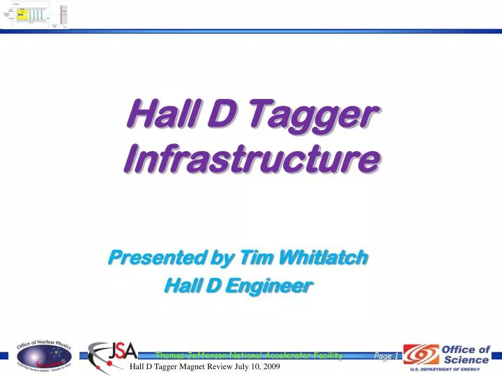
Hall D Tagger Infrastructure . Presented by Tim Whitlatch Hall D Engineer. What will be presented?. Overall layout Interfaces Infrastructure Electrical system requirements and layout Cooling systems requirements Assembly/Installation of the Tagger components Alignment ES&H Summary.

E N D
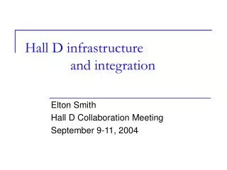
Hall D Tagger Infrastructure Presented by Tim Whitlatch Hall D Engineer
What will be presented? • Overall layout • Interfaces • Infrastructure • Electrical system requirements and layout • Cooling systems requirements • Assembly/Installation of the Tagger components • Alignment • ES&H • Summary
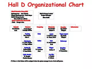
Who is working on the mechanical design/fab? • Chuck Hutton – Lead Designer - design integration, Start counter, FDC, Pair spectrometer, scheduling • William Crahen - Mechanical Engineer- FDC, TOF, FCAL, conventional analysis and FEA • George Biallas– Senior Engineer (50%) – Solenoid cryogenics, magnetic fields and mechanical integration design • VladislavRazmyslovich– Designer – CDC, gas systems, collimator and beamline, target • James Lagner– Contract Designer – BCAL, Tagger magnet, vacuum chamber and Hodoscope • Floyd Martin – Contract Designer– Solenoid magnetic field FEA, cryogenic test setup and mechanical design • Mark Stevens – Technician – FDC and solenoid • Jim Stewart – Scientist/Engineer – Tagger (gone to BNL)
Photon beam and experimental area Tagger area Hall D North linac Electron Beam dump East arc Counting House Tagger Coherent Bremsstrahlung photon beam Radiator Photon Beam dump Pair Spectrometer Top View 75 m Solenoid- Based detector Collimator Electron beam / dump Tagger Area Experimental Hall D Collimator Cave
Tagger Area Permanent Magnet North Wall AC ducts Vacuum gages and pump Beam Current Monitor Photon Beamline Beamline encasement to Hall D Quad Radiator Vacuum Chamber Electron dump Tagger Magnet Truck ramp entrance Shielding
Interfaces • Civil (utilities, structural loading) • Utilities (LCW, Chilled water, power…) • Structural • Accelerator • Vacuum • MPS • PSS • Electron Dump • Cryogenics • Survey and alignment
Hall D Complex – Site Layout N Service Building (Power Supplies, LCW equipment) Counting House Cryogenics Plant Connection to existing tunnel Collimator Enclosure Photon Beam Pipe (10” concrete encased pipe) Hall D 109’ – 10 ¾” 102’ – 1 ¼” 70’ – 5” 90’ – 7” 161’ – 6¾” 41’ 98’ – 9 ½” Personnel & truck access ramp Personnel & truck access ramp Tagger Area: Tagger magnet separates the electrons and photon beam continues to Hall D Dimensions are driven by the beam line requirements Hall D Complex Drawings A001
Tagger Service Building/Tagger Hall Service Building 28 - 4” ducts for power and signal cables Electrical panels LCW from tunnel extension (85GPM available) • Magnet power supplies in service building • Vacuum gage controllers in service building • Tagger Hall temp. controlled (70°F, 55% hum max)
Electrical System Requirements AC Power – “clean” and “utility” • All electronics crates grounded to ground grid • Extra power and conduits available for growth
Installation Concept I-beam track • Magnet built in pieces < 25 tons • Support plates embedded in ceiling • Strong back for handling vacuum vessel needed Magnet 25 Ton carriage Support plates
Hall D Tagger Magnet Design Review July 10, 2009 I-beam strongback 3-point adjustment ±9mm vertical adjustment ±1cm x-y adjustment Vacuum chamber support Stands grouted in place after alignment Final magnet alignment after install TaggerSupport Strongback Hodoscope attach points Adjustment cartridges Vacuum Chamber supports Base stands
Installation View • Pieces unloaded from truck bed and put on rollers • Pieces lifted from rollers onto stands • See movie Pieces lifted from floor Truck backs into area
ALIGNMENT CONSIDERATIONS • Network of fiducial monuments around the tagger hall tie into the main accelerator within 0.75 mm. • Visible fiducials on tagger steel for alignment relative to electron beam • Measure alignment with magnet off and magnet on
Environmental Safety & Health Prior to installation safety review… • Task Hazard Analysis • HDList • TOSP/SOP • Specific Procedures written • Use Design Authority for pressure systems • Design Review
Environmental Safety and Health • Personnel Safety System (PSS) • Magnetic door locks • Vestibule cameras • Run/stop boxes • ODH alarms • Radiation Alarms • Magnet power alerts/barricades • Exhaust fans • Fire suppression system
Environmental Safety and Health • Machine Protection System (MPS) • Vacuum monitoring • Magnet temperature monitoring • Equipment Protection • Temperature monitoring (Electronics and magnets) • Radiation monitoring • Current/voltage monitoring • Klixons to shut off magnets
Summary • Interfaces have been addressed • Infrastructure consistent with magnet requirements • ES&H plans in place – to be developed further as the tasks grow near. • Installation and alignment addressed.
Tagger Area Permanent Magnet (MPS) North Wall AC ducts Vacuum gages, Ion gages and pump (MPS) Photon Beamline Beamline encasement to Hall D Quad Radiator Vacuum Chamber Electron dump Tagger Magnet Truck ramp entrance Shielding
Use optical means to determine relation between pole edges and fiducials on each slab within 50 microns Laser tracking fiducial targets on tagger magnet to position relative to monuments within 40 microns Absolute position relative to accelerator within 0.75mm Tagger Achievable Alignment Targets visible after install on upstream end
Vacuum Chamber O-ring groove along entire edge, top and bottom Skin, 0.25 inch plate Cut out for photon beam tube Stiffening ribs 1 inch plate
Tagger End View • Adjustment cartridges use wedge type for vertical • Sliders for X-Z • +/- 2cm horizontal plane adjustment • +/- 9mm vertical adjustment Adjustment cartridges
Hall D AC Power Requirements Room to grow! Total Required 685 kVA Total Available > 1000 kVA
Hall D Equipment Cooling Requirements • Chilled water used to supply cooling to heat exchangers • FDC and collimator use liquid cooling • CDC, BCAL, FCAL and racks use air cooling
Hall D Complex - Cooling Requirements With room to grow!