Download
1 / 16
160 likes | 407 Views
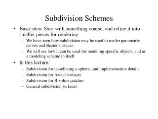
Mesh Parametrization with Butterfly Subdivision Scheme. CGIV, 26~29 July 2004, Penang, Malaysia. Graduate School of Software Dongseo University, Busan, Korea Byung Gook Lee and Chung Jae Lim Nam Woo Kim, d5302010@dongseo.ac.kr. Abstract.

E N D
Mesh Parametrization with Butterfly Subdivision Scheme CGIV, 26~29 July 2004, Penang, Malaysia Graduate School of Software Dongseo University, Busan, Korea Byung Gook Lee and Chung Jae Lim Nam Woo Kim, d5302010@dongseo.ac.kr
Abstract Parametrization of a surface triangulation S(G;X) is any planar triangulation P which is isomorphic to G Subdivision is a very powerful paradigm for the generation of smooth curves and surfaces of arbitrary topology This paper proposes an approach of parametrization using subdivision technique to decrease the distortion
(0,1) (1,1) (0,0) (1,0) Texture Mapping The method how to map a bitmap image onto the 3D model Improvement of reality by using even for a small number of vertices Bitmap Texture coordinate
(s,t) v v z t y s x parametrization in 2D triangular mesh in 3D Parametrization • Embedding 3D mesh to 2D parameter space • Requirements • Distortion minimization • One-to-one mapping
Convex Combination Determine shape of parameter space Map boundary vertices onto a convex polygon Determine coefficients for the inner vertices To set each u to be a convex combination of its neighbours Solve a linear system Ax = b Benefit : simple and fast, one-to-one embedding Drawback : high distortions in small mesh 1-ring neighborhood in parametric space parameterization with rectangular boundary 3D mesh
0 ~ ~ a a = ~ ~ ~ ~ b b 0 0 + + a a A a‘ R2 b‘ B Boundary Points x1, x2, x3, ... , xn:Interior points xn+1, xn+2, xn+3, ... , xN: Boundary points a‘+b‘ a : Distance between A and B in 3D mesh b : Distance between B and C in 3D mesh
Coefficient Computation Uniform Parametrization [Tutte 63] Shape-preserving Parametrization [Floater 97]
= ( ) ¸ d f l l E i j 1 ( ) ¸ E 2 i j 0 ( ) = o r a ¸ > 2 E = i j 0 i j i 2 i j ; = i j ; f g h F i 1 2 3 ; 2 N N o r e a c n ; ; ; : : : ; X X ¸ ¸ 1 u u = = i j i i j j j j 1 1 = = P5 P3 P4 y P P2 P6 P1 x Uniform Parametrization • Uniform Parametrization [Tutte 63] • ui is the barycentre of its neighbours di : The number of neighbours ui
Shape-preserving Parametrization • Shape-preserving parametrization [Floater97] • Conformal mapping of 1-ring neighborhood • Average of barycentric coordinates 1-ring neighborhood in 3D conformal mapping onto 2D averaging barycentric coord.
d d i i X X ¸ ¸ P P 1 = = k i j i j ; : k k ; ; ( ) P P P a r e a k k 1 1 2 3 = = ; ; k k k k ( ) ¸ P P 1 ¡ ¡ ¸ ¸ ¸ P P P P + + x x = = i j k j i = ; i j i j i j 1 2 3 1 ( ) k P P P ; 1 2 3 a r e a ; ; ; 1 2 3 ; ; ( ) ( ) = ( ) µ P P P 2 2 a n g ¼ a n g x x x = k k k k j i j i 1 1 + + ( ) P P P ; ; ; ; a r e a 1 3 ; ; ¸ = i j ; 2 ( ) P P P ; a r e a 1 2 3 ; ; ( ) P P P a r e a 1 2 ; ; ¸ = i j ; 3 ( ) P P P ; a r e a 1 2 3 ; ; Step 1 : A vertex is selected and sub triangles are created according to the neighbours. These drawings have to satisfy the below conditions:
P P P P ( ) ( ) l l l 1 + r r d d d i 1 i i X X X ¸ k d 1 P P ¢ ¢ ¢ ¹ 1 0 ¸ = = k l i j i ¹ ¹ ¹ = ; = ; ; : k k l k k l k l d ; ; ; : : ; ; ; i l 1 = k k 1 1 = = Step 2 : If di≥3 rotation has to be done in order to draw triangles. In each rotation, a straight line is drawn from the originated vertex through middle point until it meets the sub mesh’s boundary. This will results a triangle as shown below
2w -w -w 1/2 1/2 -w 2w -w Subdivision and Butterfly schemes Subdivision defines a smooth curve or surface as the limit of a sequence of successive refinements It is a subdivision scheme for surfaces which used triangular topology
Approach 1 Run Butterfly Subdivision Schemes Initial mesh Compute coefficients i,j (inner vertices + boundary vertices) parametrization
Approach 2 Compute coefficients i,j (inner vertices + boundary vertices) Initial mesh Run Butterfly Subdivision Schemes parametrization
Conclusion • M1=SM0 • Approach 1 is expensive • Why? : more computational time and memory to solve the linear system • Approach 2 is easy to calculate the coefficients • We have to compare these two approaches with an appropriate distortion measure # of vertices of M1= # of vertices of M0 + # of edges of M0