Download
1 / 43
430 likes | 588 Views
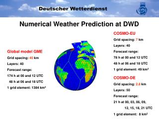
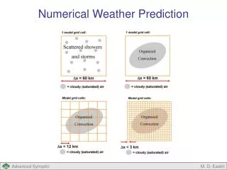
AN ECMWF LECTURER. Numerical Weather Prediction Parametrization of diabatic processes The ECMWF cloud scheme. tompkins@ecmwf.int. G(q t ). q t. y. q s. x. The ECMWF Scheme Approach. 2 Additional prognostic variables : Cloud mass (liquid + ice) Cloud fraction

E N D
AN ECMWF LECTURER Numerical Weather Prediction Parametrization of diabatic processesThe ECMWF cloud scheme tompkins@ecmwf.int
G(qt) qt y qs x The ECMWF Scheme Approach • 2 Additional prognostic variables: • Cloud mass (liquid + ice) • Cloud fraction • Sources/Sinks from physical processes: • Deep and shallow convection • Turbulent mixing • Cloud top turbulence, Horizontal Eddies • Diabatic or Adiabatic Cooling or Warming • Radiation, dynamics... • Precipitation processes • Advection C Some (not all) of these are derived from a distribution approach
Basic assumptions • Clouds fill the whole model layer in the vertical (fraction=cover) • Clouds have the same thermal state as the environmental air • rain water/snow falls out instantly but is subject to evaporation/sublimation and melting in lower levels • cloud ice and water are distinguished only as a function of temperature - only one equation for condensate is necessary
3 1 2 4 5 1.Convective Detrainment 2. (A)diabatic warming/cooling 3. Subgrid turbulent mixing 4. Precipitation generation 5. Precipitation evaporation/melting Schematic of Source/Sink terms cloud
ECMWF prognostic scheme - Equations Cloud liquid water/ice ql Cloud fraction C A: Large Scale Advection S: Source/Sink due to: SCV: Source/Sink due due to shallow convection (not post-29r1) SBL: Source/Sink Boundary Layer Processes (not post-29r1) c: Source due to Condensation e: Sink due to Evaporation Gp: Precipitation sink D: Detrainment from deep convection Last term in liquid/ice : Cloud top entrainment (not post-29r1)
Linking clouds and convection Basic idea use detrained condensate as a source for cloud water/ice Examples Ose, 1993, Tiedtke 1993, DelGenio et al. 1996, Fowler et al. 1996 Source terms for cloud condensate and fraction can be derived using the mass-flux approach to convection parametrization.
(-Muql)k-1/2 (-Muql)k+1/2 Convective source terms - Water/Ice (Muqlu)k-1/2 k-1/2 Standard equation for mass flux convection scheme ECHAM, ECMWF and many others... Duqlu k k+1/2 (Muqlu)k+1/2 write in upstream mass-flux form
(MuC)k-1/2 (MuC)k+1/2 Convective source terms - Cloud Fraction Can write similar equation for the cloud fraction Factor (1-C)assumes that the pre-existing cloud is randomly distributed and thus the probability of the convective event occurring in cloudy regions is equal to C k-1/2 Du k k+1/2
Convection Cloud formation dealt with separately Turbulent Mixing Cloud formation dealt with separately Stratiform cloud formation Local criterion for cloud formation: q > qs(T,p) Two ways to achieve this in an unsaturated parcel: increase q or decrease qs Processes that can increase q in a gridbox Advection
but There are numerical problems in models u t t+Dt Advection and cloud formation Advection does not mix air !!! It merely moves it around conserving its properties, including clouds. Because of the non-linearity of qs(T), q2 > qs(T2) This is a numerical problem and should not be used as cloud producing process! Would also be preferable to advect moist conserved quantities instead of T and q
= w Stratiform cloud formation Postulate: The main (but not only) cloud production mechanisms for stratiform clouds are due to changes in qs. Hence we will link stratiform cloud formation to dqs/dt.
C G(qt) 1-C qt Stratiform cloud formation The cloud generation term is split into two components: Existing clouds “New” clouds And assumes a mixed ‘uniform-delta’ total water distribution
Stratiform cloud formation: Existing Clouds C G(qt) qt Already existing clouds are assumed to be at saturation at the grid-mean temperature. Any change in qs will directly lead to condensation. Note that this term would apply to a variety of PDFs for the cloudy air (e.g. uniform distribution)
C G(qt) 1-C qt Stratiform cloud formation Formation of new clouds Due to lack of knowledge concerning the variance of water vapour in the clear sky regions we have to resort to the use of a critical relative humidity RH>RHcrit We know qe from similarly RHcrit = 80 % is used throughout most of the troposphere
RH<RHcrit C G(qt) 1-C qt Term inactive if RH<RHcrit Perhaps for large cooling this is accurate? • As we stated in the statistical scheme lecture: • With prognostic cloud water and here cover we can write source and sinks consistently with an underlying distribution function • But in overcast or clear sky conditions we have a loss of information. Hence the use of Rhcrit in clear sky conditions for cloud formation
C G(qt) qt Evaporation of clouds no effect on cloud cover Processes: e=e1+e2 • Large-scale descent and cumulus-induced subsidence • Diabatic heating • Turbulent mixing (E2) Note: Incorrectly assumes mixing only reduces cloud cover and liquid! GCM grid cell Dx
C G(qt) 1-C qt Subsequent Warming of same magnitude: No effect on cloud cover C G(qt) 1-C qt Process not reversible Problem: Reversible Scheme? Cooling: Increases cloud cover
Precipitation generation Mixed Phase and water clouds Sundqvist, 1978 C0=10-4s-1 C1=100 Collection C2=0.5 Bergeron Process qlcrit=0.3 g kg-1
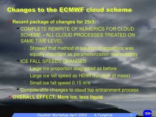
For IWC<100 - explicitly calculate ice settling flux McFarquhar and Heymsfield (1997) Heymsfield and Donner (1990) Precipitation generation – Pre 25r3 Pure ice clouds (T<250 K) Two size classes of ice, boundary at 100 mm Ice falling in cloud below is source for ice in that layer, ice falling into clear sky is converted into snow IWC>100 falls out as snow within one timestep
For IWC<100 - explicitly calculate ice settling flux McFarquhar and Heymsfield (1997) Heymsfield and Donner (1990) Precipitation generation – Post 25r3 Pure ice clouds (T<250 K) Two size classes of ice, boundary at 100 mm Ice falling in cloud below is source for ice in that layer, ice falling into clear sky is converted into snow IWC>100 falls according to Heymsfield and Donner (1990) Small Ice has fixed fall speed of 0.15 m/s
Numerical Integration In both prognostic equations for cloud cover and cloud water all source and sink terms are treated either explicitly or Implicitly. E.g: Solve analytically and exactly as ordinary differential equations (provided Kj>0)
Numerical Integration • How is this accomplished? • If a term contains a nth power for example: • The first order approximation is used: Beginning of timestep value
Numerical Aspects – Ice fall speeds • Remember the original ice assumptions? “IWC>100 falls out as snow within one timestep” – V = CFL limit Solved implicitly to prevent noise Can calculate fall speed implied by CFL limit
Resulting Ice Fall Speed T511: pre-25r3 LARGE ICE SMALL ICE IN CLOUD ICE MIXING RATIO (KG/KG)
SMALL ICE LARGE ICE IN CLOUD ICE MIXING RATIO (KG/KG) Resulting Ice Fall Speed T95: pre-25r3 (corrected at 25r3)
Real advection Perfect advection w Numerical Aspects - Vertical Advection Problem: we neglect vertical subgrid-scales
Solution (not very satisfactory): Only allow sedimentation of cloud mass into existing cloudy regions, otherwise convert to snow – Results in higher effective sedimentation rates AND vertical resolution sensitivity Ice flux Snow flux Ice sedimentation: Further Numerical Problems Since we only allow ice to fall one layer in a timestep, and since the cloud fills the layer in the vertical, the cloud lower boundary is advected at the CFL rate of Dz / Dt
Numerical Aspects - Ice settling Problem : A “bad” assumption and numerics (always imperfect) lead to a realistic looking result. Start with single layer ice cloud in level k - expect that settling moves some of the ice into the next layer and that some stays in this layer due to size distribution. AssumeDt = Dz / vice and ignore density 1. We implicitly assume that all particles fall with the same velocity - wrong Perfect numerics in this case - explicit scheme: Correct but not as expected 2. Use analytical integration as expected butincorrect
100 vs 50 layer resolution which is which? k k+1 Ice flux Snow flux Sink at level k depends on dz This is correct, but if then converted to snow and “lost” will introduce a resolution sensivity
Planned Revision for 29r3 (sept 2005)To tackle ice settling deficiency Advected Quantity (e.g. ice) fall speed Options: (i) Implicit numerics (ii) Time splitting (iii) Semi-Lagrangian Constant Explicit Source/Sink Implicit Source/Sink (not required for short timesteps) Implicit: Upstream forward in time, j=vertical level n=time level what is short? Solution Note: For multiple X-bin bulk scheme (X=ice, graupel, snow…) with implicit (“D” above) cross-terms leads to set of X-linear algebraic equations
100 vs 50 layer resolution Improved Numerics in SCM Cirrus Case 29r1 Scheme cloud ice cloud fraction time which is which? 29r3 Scheme cloud ice cloud fraction time evolution of cloud cover and ice
Melting Occurs whenever T > 0 C Is limited such that cooling does not lead to T < 0 C Precipitation evaporation and melting Evaporation (Kessler 1969, Monogram) Newtonian Relaxation to saturated conditions
Precipitation Evaporation Mimics radiation schemes by using a ‘2-column’ approach of recording both cloud and clear precipitation fluxes This allows a more accurate assessment of precipitation evaporation NUMERICS: Solved Implicitly to avoid numerical problems Jakob and Klein (QJRMS, 2000)
Clear sky region Grid slowly saturates Precipitation Evaporation • Numerical “Limiters” have to be applied to prevent grid scale saturation Clear sky region Grid can not saturate
Precipitation Evaporation • Threshold for rainfall evaporation based on precipitation cover 100% Critical relative humidity for precipitation evaporation RHcrit 70% Clear sky Precipitation Fraction 1 0 • Instead can use overlap with clear sky humidity distribution • Humidity in most moist fraction used instead of clear sky mean Clear sky
Cirrus Clouds, new homogeneous nucleation form for 29r3 • Want to represent super-saturation and homogeneous nucleation • Include simple diagnostic parameterization in existing ECMWF cloud scheme • Desires: • Supersaturated clear-sky states with respect to ice • Existence of ice crystals in locally subsaturated state • Only possible with extra prognostic equation… GCM gridbox C Clear sky Cloudy region
Unlike “parcel” models, or high resolution LES models, we have to deal with subgrid variability GCM gridbox qvenv=? qvcld =? clear cloud I F S C Three items of information: qv, qi, C (vapour, cloud ice and cover) • We know: qc occurs in the cloudy part of the gridbox • We know: The mean in-cloud cloud ice • What about the water vapour? In the bad-old-days was easy: • Clouds: qvcld=qs • Clear sky: qvenv=(qv-Cqs)/(1-C) (rain evap and new cloud formation)
Lohmann and Karcher: Humidity uniform across gridcell 2. qv qv Klaus Gierens:Humidity in clear sky part equal to the mean total water 3. qv+qi qv-qi(1-C)/C My assumption: Hang on… Looks familiar??? 4. (qv-Cqs)/(1-C) qs The good-new-days: assume no supersaturation can exist GCM gridbox C qvenv qvcld The bad old days No supersaturation 1. (qv-Cqs)/(1-C) qs
Lohmann and Karcher: Humidity uniform across gridcell 2. qv qv From Mesoscale Model qvenv qvcld GCM gridbox Critical Scrit reached uplifted box 1 timestep qvcld: reduces as ice is formed qi: increases 1 timestep qvenv=qvcld Artificial flux of vapour from clear sky to cloudy regions!!! Assumption ignores fact that difference processes are occurring on the subgrid-scale
My assumption: Hang on… Looks familiar??? 4. (qv-Cqs)/(1-C) qs From GCM perspective qvenv qvcld GCM gridbox Critical Scrit reached Difference to standard scheme is that environmental humidity must exceed Scrit to form new cloud uplifted box qvcld: reduces to qs qvenv unchanged qi: increases microphysics qi: decreases qvenv=unchanged No artificial flux of vapour from clear sky from/to cloudy regions Assumption seems reasonable: BUT! Does not allow nucleation or sublimation timescales to be represented, due to hard adjustment
B C A RH PDFat 250hPaone month average Aircraft observations A: Numerics and interpolation for default model B: The RH=1 microphysics mode C: Drop due to GCM assumption of subgrid fluctuations in total water
Summary of Tiedtke Scheme • Scheme introduces two prognostic equations for cloud water and cloud mass • Sources and sinks for each physical process - • Many derived using assumptions concerning subgrid-scale PDF for vapour and clouds JMore simple to implement than a prognostic statistical scheme since “short cuts” are possible for some terms. Also nicer for assimilation since prognostic quantities are directly observable LLoss of information (no memory) in clear sky (a=0) or overcast conditions (a=1) (critical relative humidities necessary etc). Difficult to make reversible processes. • Nothing to stop solution diverging for cloud cover and cloud water. (e.g: liquid>0 while a=0). More unphysical “safety switches” necessary. Last Lecture: Validation!
M=0 s-1 ExampleProblem M=1/3600 s-1 Gridbox • Convection detrains into a clear-sky grid-box at a normalized rate of 1/3600 s-1. This is the highest level of convection so there is no subsidence from the layer above (see picture). How long does it take for the cloud cover to reach 50%? State the assumptions made. • The detrained air has a cloud liquid water mass mixing ratio of 3 g kg-1. If the conversion to precipitation is treated as a simple Newtonian relaxation (i.e. [dql / dt]precip = ql / tau) with a timescale of 2 hours, what is the equilibrium cloud mass mixing ratio? M=1/3600 s-1 Answers: (1) 42 minutes (2) 2 g kg-1.