Download
1 / 10
100 likes | 202 Views
DCLL TBM Reference Design Setting up parameters for the Costing Exercise and For the Preliminary Design Phase. Mission: Design, fabricate and commission the first DCLL blanket to be tested in ITER on day-one, to support the DCLL module testing goals during

E N D
DCLL TBM Reference Design Setting up parameters for the Costing Exercise and For the Preliminary Design Phase Mission: Design, fabricate and commission the first DCLL blanket to be tested in ITER on day-one, to support the DCLL module testing goals during the HH phase of ITER and to prepare the module design and ancillary equipment for subsequent modules and corresponding tests. • New TBM geometry • Reference design and parameters • Design temperatures • Ancillary equipment Presented by C. Wong for the TBM team TBM conference call, August 31, 2005
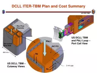
Port frame Recent change in frame thickness to 20 cm changed the dimensions and power generation of the DCLL TBM. DCLL Design approach and Configuration remain the same. New module dimensions in mm 413 New frame thickness at 20 cm TBM Shield 1660 Dog leg Test port frame Cross-section 484 Flat surface will be used
US DCLL TBM module All FS structures are He-cooled @ 8 MPa PbLi self-cooled flows in poloidal direction SS frame Front FCI is the Thermal and MHD Insulator lining all PbLi channels FS structure PbLi in PbLi out He in Back He out PbLi in FW He counter flow PbLi out 2mm Be front face
DCLL Design Parameters
DCLL Parameters Con’t
DCLL TBM Bypass Loop Schematic Pump 360 C Tritium extraction tank Valve off 19.26 kg/s bypass line 180 C DCLL TBM 360 C 0 kg/s PbLi loop 8 MPa Helium loop PbLi/He Heat Exchanger Concentric pipe with FCI 470 C PbLi mixing tank 470 C 19.26 kg/s 0.4 MW 300 C Higher PbLi exit temperature can be achieved without requiring high-temperature materials for external piping/HX/TX. This can be achieved by turning the bypass valve “on” to allow mixing a lower temperature stream with the high-temperature stream in the PbLi mixing Tank
DCLL Design Temperatures Reference TBM operation limits Higher performance operation limits FS Tmax ≤ 550° C ≤ 550° C FS/PbLi < 500° C < 500° C SiC/PbLi < 500° C < 700° C SiC Tmax < 500° C < 700° C Coolant temperature range: 360° C < He < 440° C 360° C < He < 440° C 360° C < PbLi ≤ 470° C 450° C < PbLi ≤ 650° C For the DCLL TBM higher PbLi exit temperature ~650° C can be achieved via the bypass loop without requiring high-temperature materials for external piping/HX/TX.
Primary He Coolant Loop TCWS Secondary He Coolant Loop TCWS Test Port Pb-Li Primary Coolant Loop Transporter Area DCLL He and PbLi Circuits Corresponding to Ancillary Equipment
DCLL Ancillary Circuits Design Parameters Aim for testing flexibility
Helium and PbLi equipment and dimensions have been scoped and ready for preliminary costing exercise PbLi loop from TBM to transporter Primary He and Secondary He Ancillary equipment at TCWS @~70 m away from the TBM