Download
1 / 15
160 likes | 262 Views
Setting the Parameters on the MICROMASTER. Start from the default parameter settings on the MICROMASTER. If necessary, set the default with P0010 = 30 and P970 = 1. There are two ways of setting the bus address: Set P0003 = 3 and set the bus address in P0918.

E N D
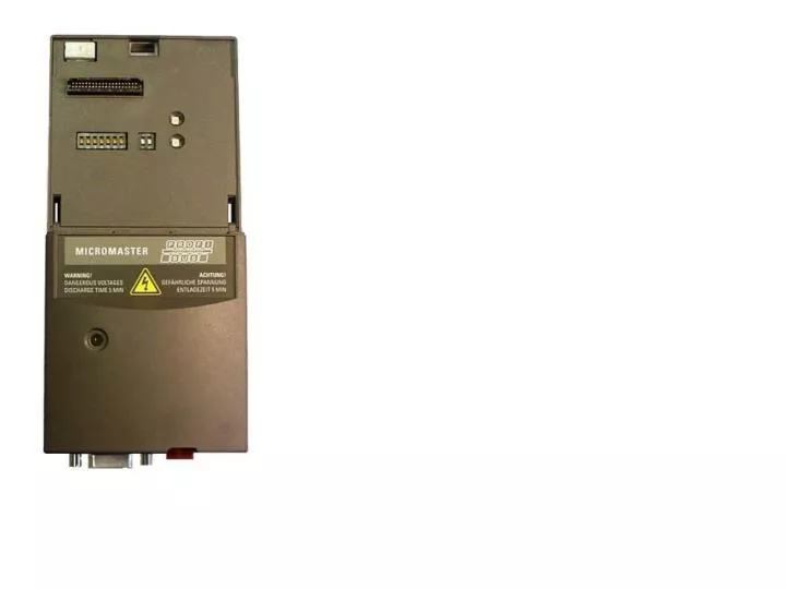
Setting the Parameters on the MICROMASTER • Start from the default parameter settings on the MICROMASTER. If necessary, set the default with P0010 = 30 and P970 = 1. There are two ways of setting the bus address: • Set P0003 = 3 and set the bus address in P0918. • Set the bus address on the DIP switches (the block of switches on the left, least significant bit is on the left). DIP switch settings take effect when the MICROMASTER is next powered up, and override P0918. • Set P0700 = 6 and P1000 = 6; this allows full Profibus control. MM420 MICROMASTERS with 1.05 software (see r0018) have P2040 default value 0 (Profibus monitoring time, in ms); we recommend it is set to 20 to allow the drive to trip F0070 and stop when there is a Profibus fault (e.g. connector pulled out), or the PLC goes to STOP. Other MICROMASTERS already have 20ms as a default value.
Principe PPO 3 Adressen instellen. b.v. 100 – 103 (3 RIJEN!)
Start with setting the speed setpoint (before starting)., once you start it through Control Word 1. A play around with the numerical value and see what happens to the drive speed, once it is started. You can change the speed setpoint at any time you need to.To actually start and stop the drive, you must set Control word 1. In the document I suggested, there is an explanation of each bit in that word. But for starters, write a hex value of 047E to PQW 256, then write 047F to the same address (there must be a rising edge on bit 0 of the Control word 1 for the drive to respond): the drive should start and ramp up to the speed setpoint you selected in Control Word 2. Now write 447E to the same address: the drive should reverse the rotation of the motor. Writing (hex)047E or 447E to PQW 256 will stop the drive; writing 0 to PQW 258 will also stop it (speed reference = 0%).Hope this helps,Daniel Chartier
INFO - algemeen • Control word 1 • for binary input control of the drive, start, stop, jog, rotation • PQW100 • Om teschrijven • PIW 100 • Om status tebekijken • Control Word 2 • speed setpoint = HEXADECIMAAL GETAL • PQW 102 • for writing • PIW 102 • for reading.
Control Word 1 PIW100.XX Klaar om te starten
Oplossing? • 1. Snelheid wegschrijven in CONTROL WORD 2 • To set the speed setpoint (12 bits), write (MOVE) the hex value 4000 to address PQW102 (Control Word 2); • 0 x 1 + 0 x 16 + 0 x 16² + 4 x 16³ = 4096 • the drive will run at 100% of the max. parametrized speed • Noodzakelijksomsomgetallenomtevormennaareenanderformaat. • hex value of 2000 will make it run at 50% of the max. parametrized speed; a hex value of 1000 will make it run at 25%....