Download
1 / 8
80 likes | 169 Views
IMPACT OF FRAME DESIGN AND FRAME REPLACEMENT PROCEDURE ON DCLL TBM By Mo Dagher Presented by Clement Wong. TBWG-16 meeting, November, 15-17, 2005, Beijing, China.

E N D
IMPACT OF FRAME DESIGN AND FRAME REPLACEMENT PROCEDURE ON DCLL TBM By Mo Dagher Presented by Clement Wong TBWG-16 meeting, November, 15-17, 2005, Beijing, China
Using a 2 frame/port frame design may be advantageous to the DCLL TBM design. However, more studies are needed in order to make a final assessment of this design option. • Advantages are: • Flexible Design Options Related to Shielding, Support and Pipe Penetrations. • Independent and Flexible Testing Procedure and Schedule. Reduced Impact of Port Sharing Party on the other TBM Operation. Since it would be possible to remove one side only if needed. • Availability of Half port Plug if sharing TBM is not ready. • Smaller TBM/Frame assembly size makes it easier to handle. • Some associated issues are: • Additional coolant lines for each frame, thus requiring more port space and more RH operations to remove and replace both Frame Assemblies in each port. • Smaller frame size is different than the standard equatorial port plug thus requiring special handling tools. FRAME DESIGN CONCEPT (1 Frame/port Vs 2 Frames/port)
PERMANENT VS REMOVABLE BACK-SIDE SHIELD STRUCTURE • DCLL TBM design should retain the flexibility of a dedicated shielding design and flexible supports due to the special requirements associated with the concept. However compatibility with the ITER proposed Frame interface will be maintained. • Using the removable back side shield concept (Lip Seal) may be an acceptable option, but the shield support design must take into account the piping requirements of the DCLL TBM. • The use of concentric pipe and the requirement to drain the LiPb after shut down restricts the size and location of the concentric pipe.
LOCATION OF CONCENTRIC DRAIN PIPE Port side view Plasma side view Port side view Plasma side view Permanent back-side shields Removable back-side shields Pb-Li Concentric Located at a higher Level will not drain TBM completely Pb-Li Concentric Pipe location at lowest point of TBM for Drainage
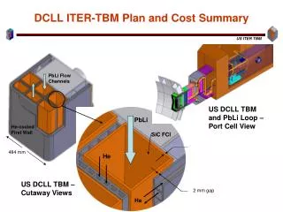
TBM PENETRATIONS AND SUPPORT STRUCTURES PbLi Concentric Pipe • Shielding design and TBM Support system should allow design flexibility in locating the piping penetrations and flexible supports. • PbLi Inlet/Outlet concentric pipe is located at the bottom portion, He coolant lines are located in the center, they may interfere with the flexible support locations but can be resolved by design.
TBM ASSEMBLY WITH FLEXIBLE SHIELDING CONCEPT CONCENTRIC PIPE PENETRATION Pb-Li concentric pipe must be pre-attached to TBM during assembly because of access issues Internal bore tool cannot be used on concentric pipe, only orbital welding/cutting tools will be used behind the shield
QUESTION: WHERE IS THE VACUUM VESSEL CLOSURE PLATE? How will pipe penetrations through VV plug be handled?
RH GRIPPERS DESIGN? Note Details of interfaces between TBM and RH tool for replacement in the hot cell are not defined yet. At present, 25 mm gap is used everywhere between TBM and Frame (except the back-side). We will need wider gaps or grooves to grip TBM. Observation: Grooves for RH Grippers must be designed in the frame, not on the DCLL TBM.