Download
1 / 25
260 likes | 269 Views
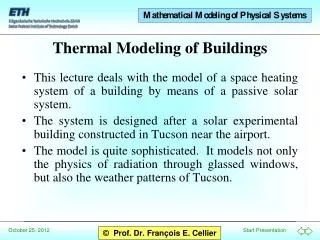
Thermal Modeling for Modern VLSI Circuits. Dr. D. Nagchoudhuri Professor EE Department, IIT Delhi. Lecture Plan. What are Thermal Issues ? Why today and not earlier? The Problems of Simulation Thermal Modeling of the MOSFET Thermal Modeling of Circuits Conclusions. Trends Today.

E N D
Thermal Modeling for Modern VLSI Circuits Dr. D. Nagchoudhuri Professor EE Department, IIT Delhi
Lecture Plan • What are Thermal Issues ? • Why today and not earlier? • The Problems of Simulation • Thermal Modeling of the MOSFET • Thermal Modeling of Circuits • Conclusions
Trends Today • Modern Circuits use Analog Interfaces • BiCMOS replacing CMOS • Bipolar Drive Circuitry Consumes Power • Short Channel Effects cause Degradation • Dimensional shrinkage continues
Thermal Issues • Temperature Rise • Temperature of neighbors • Heat dissipation in Device • Heat Conduction • Radiation • Conduction
Why today and not earlier? • Increasing Density • Increasing proximity – effect of neighbors • Increasing number • Increasing SoC => increasing Analog components • Increasing Dopings for scaling • Smaller Depletion widths • Larger Fields • Larger Leakage currents
Effect of Temperature Rise • Temperature dependent Semiconductor Parameters • Mobility • Threshold Voltage • Intrinsic Carrier Concentration • Band-Gap • Only first two parameters being considered!! • Found dominant in many cases!
Effect of Semiconductor Parameters • , VT • Changes IDS • IDS changes gm • gm affects • Gain • Bandwidth • Pole locations
The Problems of Simulation • Cost of Error in prediction enormous • SPICE Simulator –Tried and Tested • Industry Standard • SPICE simulates chip at single temperature. • Cannot show dynamic variation with temperature. • Modern Chips have devices at different Temperature.
Approach • Power Dissipation => Temperature • Temperature => Device Parameters • Device Parameters => Circuit performance • Circuit performance • Add thermal circuit • Simulate by SPICE
Device Equations • ID = 1/2 Cox (W/L) [VGS - VTh]2 • ID/ = 1/2Cox (W/L) [VGS - VTh]2 • ID/ T = ( ID/ )( / T ) • ID/ VTh = Cox (W/L) [VGS - VTh] • ID = ( ID/ ) +( ID/ VTh) VTh
Temperature Dependence of Parameters • VTh(T) = VTh(Tref) - k1(T - Tref) • k1 = - VTh/ T => 0.5-4 mv/K • (T) = (Tref) [T/Tref]-k2 • / T = - k2 (Tref)/T • (T) and VTh(T) are decreasing functions of temperature.
The Transistor with Thermal Circuit G D CTh RTH N0 Self-Heating Node V2,V3, …Vn B S
The Feedback Loop IDS Power Temperature Device Parameters
Sensing Current iDS iDS H CCVS => v0 = KiDS
Self Heating Power vDSiDS V1 V0 => N0 E1 V2 VCVS => V0 = KV1V2 = vDSiDS = P0 V1 = KiDS V2 = vDS
Power => Temperature • Temperature rise proportional to Power dissipation • Rate of Temperature Rise determined by thermal time constant • Rth => Thermal Resistance • Cth => Thermal Capacity
RTh Tout CTh Thermal Resistance and Capacity
Computing Temperature = Tavg V1 V0 => Tavg E2 V2,V3, …Vn VCVS => V0 = K1 V1 + {V2,..Vn} V1 = Self Heating {V2,..Vn} = Neighbor Node Temperatures
Threshold Voltage Dependence V1 V0 E3 V2 VCVS => V0 = KV1 + K2 V2 V2 = K3Tavg ; V1 = Vin - VT V0 = VTh
Mobility Variation with Temperature V0 V1 G VCCS => V0 = G V1 V1 = Tavg V0 = I
The Model with Controlled Sources D N0 H E1 G E3 G E2 N1..Nn S B
Conclusions • Digital CMOS Circuit Power Dissipation • Leakage Current • Switching Power • Conduction during transition • Increasing Speed => Digital activity • Power = CV2f • Reducing Dimensions • Leakage • Short Channel Effects • Affects proximate analog circuits
Issues • Predict temperature from power dissipation • => 3D problem • Thermal Layout vs Area minimization • Predict Thermal Degradation • => Strong Layout Dependence • Effect of Temperature Gradients