Download
1 / 55
550 likes | 739 Views
3-D scene modeling and applications in optical and thermal remote sensing. Wenhan Qin SSAI/GSFC, NASA. Outline. History overview: the necessity from 1-D to 3-D 3-D scene rendering with Lindenmayer Systems (L-Systems) RGM (radiosity-graphics method) and TRGM

E N D
3-D scene modeling and applications in optical and thermal remote sensing Wenhan Qin SSAI/GSFC, NASA
Outline • History overview: the necessity from 1-D to 3-D • 3-D scene rendering with Lindenmayer Systems (L-Systems) • RGM (radiosity-graphics method) and TRGM • Applications in optical and thermal IR regions • LST (land surface temperature) and emissivity: modeling and inferring from satellite data
Surface Reflection BRF (bidirectional reflectance factor) defined as R(q0,q,)=pI/F0cosq0 F0(l) I q0 q φ
Vegetation BRF models • Physically-based canopy reflectance models • Link Canopy Properties With Sensor-measured Radiance • Provide Theoretical Basis For Extracting Vegetation Properties From RS • Critical inputs to land surface process models, driving biochemical models, & other biospherical functions • Albedo • Surface temperature and energy balance • Leaf area index (LAI) • Fractional photosynthetically active radiation (FPAR) absorbed by canopy • Surface roughness • Phenology
From visible/NIR to thermal IR • There are two basic diffs: • In visible/NIR, τ≈ρ; in TIR, τ«ρ • In TIR, need to add emission term to RT eq. • No fundamental difference in the physics and optics in model derivations in going from visible/NIR to thermal IR Typical leaf optical properties In principle, BRF models developed in optical domain can be applied to TIR
Background: Why 3-D models? • 1-D models – turbid medium • Based on KM (Kubelka-Munk) theory i.e., use linear differential eq. set for • 2-flux (up- & downward) or • 4-flux (up- & dnward diffuse & specular) approximation • Reps: Suits (1972); Goudriaan (1977); Cupid (Norman, 1979); SAIL (Verhoef, 1984) Consider leaf as infinitely small diffusing & absorbing particles Drawbacks • Oversimplification (leaf size >>λ, casting shadows --> ‘hotspot’ effect); • Only applicable to dense, leafy canopies; • Not suitable for directional refl calculation (because of using integrated fluxes); • Scattering coefs having to be determined empirically or semi-empirically
Decomposition Method • 1-D models – finite size medium • decompose canopy radiation field into 3-components: unscattered, single & multiple scattering • accurate solution of zero- & first-scattering by capturing • canopy hotspot effect • specular reflection from leaf surfaces • anisotropic reflectance from the soil background • estimate multiple scattering w/ 2- or 4-stream approximation or numerical methods • Reps: Kuusk (1985); Marshak (1989); Verstraete et al. (1990); Nilson (1991); Qin (1993); Liang & Strahler (1995) • Leaf as finite size scatterers with Bi-Lambertian reflectance & transmittance • Homogeneous canopy w/ given LAI (leaf area index) and LAD (leaf angle distribution)
Geometric optical BRF models • GO model w/ solid tree crowns • 4-component model (sunlit & shaded crown & soil fractions) • Ignor multiple scattering • Reps: Li & Strahler (1985), Jupp (1986) • Hybrid GO-RT model for tree crowns w/ gaps inside • Apply KM theory to estimate component reflectance due to multiple scattering • Reps: Nilson (1990,1991), Li et al (1995), Ni et al (1997), Chen & Leblanc (1997) • Drawbacks • Not suitable for trees w/o distinguishable crown • Not suitable for dense, continuous forests Basic crown setup (cones for conifers)
A Kernel-driven BRF model Scene reflectance is approximated by the linear combination of diff. Kernels (characterizing different scattering modes) BRF=fiso+ fvol•kvol+fgeo•kgeo Developed by BU group & used in MODIS BRDF/Albedo product (Strahler, et al. 1995) Added specular kernel and extended to thermal IR region by Snyder & Wan (1998) Apply to satellite pixels thru. land cover types
Challenges from natural forests: 3-dimensional, heterogenuous architectures Since all 1-D or 2-D models only work on ‘statistic’ canopies none of them suitable for a 3-D realistic scene, that’s when 3-D scene modeling comes to play a big role
3-D RT model (Myneni 1991) DART model (Gastellu-Etchegorry et al. 1996) Monte Carlo/Ray Tracing method (North 1996; Disney et al. 2000) Radiosity method (Borel et al. 1991; Goel et al. 1991; Qin & Gerstl 2000) 3-D BRF models All 3-D models need the 3-D structure rendered on computer as input
L-systems a tool for rendering 3-D objects • String language • parallel rewriting systems • e.g., rule a->b; b->ba produces: • a->b->ba->bab->babba->etc. • 0L-system: triplet (V, s, P): • V: the ALPHABET (a collection of symbols, letters & characters) • s: the AXIOM (initial word) • P: PRODUCTION rules Fractal plant
ELSYS: a high-level language • Extended L-system (ELSYS) • Grammar extensions • functions, subroutines, standard 3D shapes, animation • develop a “compiler” • 3D rendering of real scenes • Samples: trees and crops, buildings, mountains, and terrain
MELS: rendering of realistic landscape • MELS (modified extended L-systems) • generate 3-D structures mixed w/ diff objects (e.g. buildings, mountain, or plants) • capable of rendering heterogeneous natural landscapes w/ scene components in any spatial pattern over non-flat terrains • module to compute detailed information about its 3-D structures and physical properties • examples of MELS rendered scenes
aerial photos of the spruce scene/tree/twig MELS rendered spruce scene/tree/branch Sample Plot (white cross points) in a MISR pixel (white square box)
RGM/TRGM • L-system rendering of 3D scenes • Radiosity equation • Graphics based methods to compute view factors • Radiosity computation • Validation and application
Radiosity surface elements finite size, holes and clumps, and spatial correlations are retained radiative effects such as shadows and hotspot, and multiple scattering between elements are automatically, fully described any canopy Radiative transfer volume elements location, shape, and orientation of individual scattering elements is lost in the averaging process hotspot effect and multiple scattering aredifficult to consider in canopy RT formulation only for dense, leafy canopies Why Radiosity?
Radiosity flux density (of radiation) leaving a surface, consisting of 3 terms: emitted flux, reflected flux and transmitted flux Radiosity equation radiation exchange in an enclosure that contains N discrete Lambertian, finite surfaces (with 2N facets) E is the emittance (reflected incident direct & diffuse radiance plus self-emitted radiance from surface i if in TIR) F (or T) is the view factor between surface i and j (or k), i.e., the fraction of flux leaving surface i (or its backside facet) and reaching surface j (or k) Gauss-Seidel iterative approach used to solve the equation Radiosity Equation
Emittance Calculation • Ei= [Fs(i) + Fd(i)] ρi+ Fe(i) • Direct • Diffuse • Self-emission • Determine parameters • depth-sorting method to compute a (Goel et al. 1991) • Energy balance method to determine T (CUPID model) • ε from measurement data a is the lit area fraction of surface i . εis emissivity, T is surface temperature, and B is the Planck function
View Factors • Definition • view factor (F) is the fraction of flux leaving surface i (or its backside facet) and reaching surface j (or k) • Equation • V(i,j): visibility function • 1, fully visible • [1,0], partially visible • 0, obstructed
View Factors (Cont.) • Computation • unit sphere method • hemicube method • computer graphics based method (CGM) • such as sorting, Z-buffer theory • fastest way to compute F
Calculation of View Factors with CGM • Formula: • Algorithm • sphere division • polygon projection • occlusion consideration • overlap area calculation • view factor estimation • hash table for storage of view factor matrix
Validation • view factors 5 plane layers each with 400 square tiles Ns: 800 pixel space: 1024x960
sun viewer Validation (Cont.) • Projection and overlap area • Output radiosities unit cube; nadir Sun, PP
Red Band NIR Band
Hot spot (sun is right behind the view dir) Dark spot (sun is opposite of the view dir)
Applications • Virtual ‘experiment’ lab • ‘numerical’ experiment vs. traditional field experiment cheaper, faster and more efficient and versatile vs. expensive, labor-extensive, time-consuming and limited by geographic conditions • to replace field experiment as a test-bedfor new model/algorithm development (e.g., analytical, fast, approximate models) • validate & parameterize 1-D models in VIS/TIR • Sensitivity analysis for key parameters, e.g. • In optical domain, impact of LAI, vegetation cover, volumetric density on BRF • In TIR, impact of component emissivity, ground coverage, soil moisture on DBT • feasibility study (assess the potential of current sensors in retrieving model parameters from simulated BRFs and DBT) • Guide new sensor design for remote sensing of specific surface parameters through OSD (optimal sampling domain) analysis • Generate LUTs for model parameter inversion based on observed BRFs and DBTs
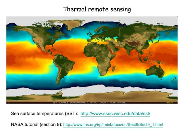
Specific Applications in TIR RS • Three major sources causing uncertainty in remote sensing of LST • atmos absorption & emission of thermal rad bias to estimate LST from satellite-measured thermal rads • surface emissivity uncertainty error in converting BT to LST • land surface heterogeneity & 3-D structure variation of BT/LST with VZA • Algorithms to deal with the first two issues • TES (temperature emissivity separation) • Split-Window method (MODIS L2 product) • Day/night method (MODIS L3 product) • Multipixel method • TRGM can help on addressing the last two issues
Surface Emissivity • Land surface emissivity varies both spatially and temporally with • soil structure, soil composition, moisture and organic matter content • vegetation-cover characteristics (species, density and structure) • surface roughness • view angles • Significant impact on LST (0.01 in SSE resulting in the retrieval errors as large as 2 K)
Soil Emissivity Arid bare soil Organic bare soil From Snyder et al. (1998)
Vegetated Scene Emissivity • Canopy fraction significantly affects scene emis due to big contrast in emis btw foliage elements and soil background • When LAI>2, canopy emis > single leaf’s emis due to cavity effects (multiple internal reflections resulting from canopy structure) • highly correlated with NDVI (corr. coef. as high as 0.94)
Surface Emissivity Determination • Lab measurement (material or component emis) • TIR models scene/pixel level emis using material/component emis as input • Empirical or semi-empirical regression method • Retrieve LST and emis simultaneously from TIR satellite data
Materials emissivity measured in the Lab • Fronapfel and Stolz in InfraMation 2006 Proceedings
TIR Models • Most 1-D and 3-D models currently used in VIS/NIR have been extended to TIR region • DART (Belo et al. 2003); TRGM (Liu et al. 2007); Kernel-driven TIR model (Snyder & Wan, 1998); 4SAIL (Verhoef et al, 2007) • Need component temperature & emis as input, which are either measured or simulated using coupled energy balance approach • Able to output DBT and DSE • e.g. Snyder & Wan (1998) output sfc emis as LUTs for global LST retrieval
TGRM over Maize Canopies MOD 2 measured DBT simulated DBT
Sensitivity of DBT to Emis Red lines (4SAIL model) T=1.0 1.5° T=2.0° 0.99 Blue circules (TGRM) εsoil=0.9 Tsoil=Tleaf=22°C Hotspot is turned off 0.9 εleaf LAI=0.5 LAI=2.0
Land type based emis from Kernel-driven model (Snyder et al. 1998) Green grass savanna Green sparse shrubs Green broadleaf forest Green needle forest
Ice and Snow Water From Snyder et al. (1998)
Flat surface w/ NDVI = a+b*ln (NDVI) Coeffs a and b derived from regression analysis (a=1.0094, b=0.047 for ndvi values from 0.2 to 0.7, Van de Griend and Owe, 1993) a non-linear egression inference scheme Chédin et al. (2004) Semi-empirical methods P is vegetation cover percentage, sub ‘s’ (‘v’) refers to soil (vegetation) (sobrino et al. 2000). • TISI (temperature-independent thermal infrared spectral index) (Becker & Li, 1990)
TES mainly used by ASTER, ATSR & AATSR Temperature Emissivity Separation w/ constraint conditions is the relative emissivities MODTRAN is used to calculate atmos dnword (Lsky) & path rad (Latm), and transmittance (). Iterative solution is sought for LST & emis
TES (Ogawa et al, 2003) • center wavelengths of ASTER channel 10 to 14 are 8.29, 8.63, 9.08, 10.66, 11.29 μm • there were significant differences (0.08 at maximum) between the classification base window emissivity map and the ASTER emissivity map
(a) Window emissivity map (8–12 mm) derived from 85 scenes of ASTER data, (b) Classification based emissivity map in 10 minutes resolution [from Wilber et al., 1999], (c) The difference between (a) and (b) (Ogawa et al, 2003)
Split-Window method • Apply linear combination of the brightness temperatures measured in atmos windows (e.g.,the AVHRR IR chs 3, 4 and 5), and use diff in atmos attenuation for these chs to remove atmos effects • LST=a + bT1 + cT2 • Give accurate results of sea surface temperature (SST) • For LST, ancillary info. on the SSE is needed because the number of unknowns always exceeds the number of measurements
Split-Window method • Generalized SW (Wan & Dozier, 1996) • Water vapor correction (Becker & Li, 1995) • Advanced split-window method (Sun & Pinker, 2003) where k is the index of the surface types and θ is the satellite viewing angle.
Day/night method July 2002 • Retrieval of LST and emissivity with CERES (Clouds and the Earth’s Radiant Energy System) data (Chen et al, 2003) • Mean 3.7-μm sfc emis derived from Terra MODIS data Oct. 2002
Multipixel method • 3-channel LST method (nighttime) (Sun & Pinker, 2003) • Hyperspectral method (Knuteson et al. 2003) • where ROBS is the observed upwelling radiance, N↑ represents the upwelling emission from the atmosphere only and N↓ represents the downwelling flux at the surface