Download
1 / 50
570 likes | 930 Views
Optical remote sensing theory, models and algorithms. Val Byfield National Oceanography Centre, Southampton, UK. with thanks to Ian Robinson and many others. Outline. Brief overview of remote sensing principles Optical theory Basic principles – absorption, scattering, (emission)

E N D
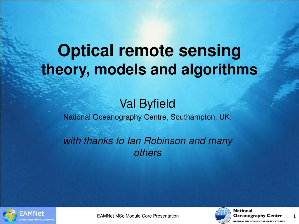
Optical remote sensingtheory, models and algorithms Val Byfield National Oceanography Centre, Southampton, UK. with thanks to Ian Robinson and many others EAMNet MSc Module Core Presentation
Outline • Brief overview of remote sensing principles • Optical theory • Basic principles – absorption, scattering, (emission) • Radiative transfer in air and water • Optical models • Different model types • Forward and inverse models • Use of models in algorithm development EAMNet MSc Module Core Presentation
Sources of energy for remote sensing • Passive • Solar illumination • Reflected by a surface • Scattered by the atmospheric content • Natural (thermal) emission • From the land, sea or ice surface • By atmospheric gases • Active • Energy provided by the sensor • Microwave pulses, laser pulses • Opportunistic • Use of other microwave emissions • GPS andother “signals of opportunity” EAMNet MSc Module Core Presentation
Electromagnetic interactions with the environment • Scattering / reflection • Occurs at solid and liquid surfaces • Depends on the material and shape of the surface • Occurs within fluids (atmosphere, seas and lakes) • Depends on properties of the fluid • Directional dependence • Spectral dependence • Absorption • Reduces the signal • Changes the spectral distribution of energy • A negative effect, difficult to detect by itself • Normally detected by measuring reflected, transmitted or scattered light and calculating loss by absorption after accounting for other effects. EAMNet MSc Module Core Presentation
Electromagnetic interactions with the environment • Emission of radiation • From surfaces • From within fluids • The reverse of absorption • Effects on speed of transmission • Depends on refractive index • Interaction with atmospheric gases of ionosphere • Phase / frequency effects at reflection • Doppler shift of reflections from moving targets (e.g. ships) • Change of pulse waveform by reflections from a distributed surface (e.g. waves) EAMNet MSc Module Core Presentation
Detecting environmental information from electro-magnetic measurements • Any environmental factor (EF) that changes the property of e-m radiation that is recorded by a particular sensor is capable of being detected / measured by that sensor. • EF can be detected if a difference in e-m radiation can be detected when the EF is removed. • EF can be measured if the change in e-m radiation varies predictably and measurably with a change in EF. • The above must be applied at top of atmosphere EAMNet MSc Module Core Presentation
Useful signal Absorbed by atmosphere Scattered out of FOV 1 + 2 + 3 = SIGNAL received if no atmosphere were present Emitted by atmosphere Atmospheric scattering into FOV Reflected by sea surface into FOV From sea surface outside FOV 4 + 5 + 6 + 7 - 2 - 3 = NOISE 7 7 7 1 1 1 6 5 5 5 4 4 6 3 3 3 2 2 2 Sea surface brightness temperature Water-leaving radiance From sea to satellite Opt. TIR MW
Optical theory applied to ocean colour Basic concepts - scattering and absorption Radiative transfer in air and water EAMNet MSc Module Core Presentation
Optical radiation includes Ultraviolet (UV): 235 - 390nm Visible (Vis): 390 - ~720nm Near infrared (NIR ): 720 - ~1500 nm Optical radiation: UV, Vis, NIR • Short-wave radiation: • The sun’s energy spectrum peaks in the visible ~ 480nm • Main energy input into the Earth system
The role of optical theory: Explain /quantify what happens to optical radiation in air and water Calculate optical parameters at different position in the system Radiative transfer Absorption and scattering The light field Inherent and appparent optical properties (AOPs and IOPs). Different optical model types Semi-empirical Semi-analytical Monte Carlo models Basic concepts Clear tropical ocean Coastal water
In the atmosphere: Absorbed or scattered by air molecules or aerosols Reflected by cloud At the air-water interface: Reflection by the surface Transmission and refraction In the water: Absorbed by water, CDOM, or phytoplankton pigments Scattered by water or particles (sediment / phytoplankton) Radiative transfer in air and water • What happens to the sun’s radiant energy in the atmosphere-ocean system?
Radiative transfer: transmission of electro-magnetic radiation through a medium (air or water). The RTE relates changes to the radiation to the physical properties of the medium. Derived by dividing the medium into many thin layers, z. The RTE quantifies these losses and contributions, so radiance , LP2, at point P2 is P z P The Radiative Transfer Equation (RTE) in brief x LP2 = LP1 - attenuation Radiance emitted in directionx Radiance scattered into directionx + +
Similar mechanism in air / water Attenuance, C - ratio between the radiation lost in a small volume of air or water and the incident radiation Scatterance, B, loss from scattering Absorbance, A, loss from absorption Attenuation includes absorption and scattering: C = A+B Transmittance T - ratio between the transmitted and incident radiation Attenuation Loss of radiation due to absorption and scattering • Scattering is most important in the visible, • Less important at thermal and IR wavelengths
c= dC / dr = - ln(1-C) / r a = dA / dr = - ln(1-A) / r b = dB / dr = - ln(1-B) / r These are known as inherent optical properties (IOPs) because they are determined by the medium (atmosphere, water) and are not changed by changes in the light field. The coefficients are additive c = a + b Atmospheric science uses the extinction coefficient instead of the attenuation coefficient c Fi r Ft Fi - Ft F1 C = CoefficientsCalculated over a thin layer of thickness r
Radiance lost between sea and sensor Radiation absorbed by atmospheric gases: O2, CO2, H2O, CH4, NO2 Aerosols: water droplets, dust RS bands chosen in ‘atmospheric windows’ Wavelengths with low absorption (high transmittance) 2 Atmospheric absorption MW Opt. TIR
Absorption and scattering by sea water (1) • a - absortpion coefficient • Absortpion increases rapidly from ~580 nm (yellow-green) and is almost complete above 700 nm (near infrared) • High water absorptionin the IR and MW - no signal from the water column • b - scattering coefficient • Scattering is strongest at short wavelengths
Scattering and absorption coefficients for water constituents depend on their concentration, C. Chlorophyll absorption: aph = Cph a*ph Scattering by plankton cells: bph = Cph b*ph ph = Cph *ph where a*, b* , b* are specific coefficients i.e. per unit concentration Absorption and scattering by sea water (2) Interaction of a beam of light with athin layer of water or air
What proportion is scattered? Absorbed radiation is ‘lost’ Changed to heat, chemical energy, fluorescence Scattered radiation retains its energy, but there is a change in direction. Single scattering albedo: w(l) = b(l) / c(l) Quantifying change in direction Volume scattering function: b(Y,l) = DI(y,l) / E(l) DV Total scattering coefficient ,b Integrate b over all angles in the sphere Backscattering coefficient ,bb Integrate b over all angles in the backward hemispere bb / b greater for molecular scattering Scattering coefficients for use in optical models
Two types of scattering • Rayleigh scattering: • Scatterers much smaller than wavelength of light (molecular) • Strongly wavelength dependent proportional to l-4 • Why the sky is blue • Main scattering in pure seawater • Mie scattering: • by particles of comparable size to wavelength of light or greater • Almost wavelength independent proportional to l-n, where n decreases with particle size • Haze, dust and water vapour in the atmosphere • Phytoplankton cells and sediment in seawater. • Rayleigh scattering << Mie scattering
Total absorption/scattering coefficient is the sum of all individual absorption/scattering coefficients. Absorption and scattering are additive • Seawater absorption: • by water • by phytoplankton pigments, • by coloured dissolved organic matter (CDOM / yellow subst.) • a = aw + aph + ays • Seawater scattering: • by water • by particles - mainly phytoplankton, but also bacteria, viruses and near coasts - sediment particles. • b = bw +bph + bsed • bb = bbw +bbph + bbsed • Atmospheric absorption: • by gases (aR)- mainly ozone, oxygen, water vapour • by aerosols (aM): water droplets, dust, smoke • a = aR + aM • Atmospheric scattering: • by air molecules (bR) • by aerosols (bM)- water droplets, dust and smoke • b = bR + bM
Direction, x, defined by q Zenith angle between horizontal plane and the upward perpendicular f Azimuth angle between a the vertical plane containing the light beam and a specified vertical reference plane (e.g. N-S or the solar plane) Geometry of a radiation field • For nadir-looking sensors q= 0o at the swath centre, and fis not defined. For swath edges viewing geometry is described by x= q, f. • W Solid angle • W = A/r2whereA is an area on the surface of a sphere of radius r. • Unit: steradians (sr), (A sphere is 4p sr.)
Sea surface effects 1 3 2 1 2
The air - water interface • Sea surface affects RS measurements • Sky reflection and sun-glint contributions • Affects downwelling light entering the water • Depends on sun angle, viewing angle and seastate • Traditional RS approach: • Avoid sun-glint by tilting the sensor • Include sky reflection in the atmospheric correction algorithms • Account for sea state primarily when there is wave braking (white-caps) • Improved accuracy by modelling surface reflection and refraction • Use Cox and Munk (1954) sea surface slope statistics from measured sun-glint • Needs estimates of wind speed • Surface modelled as many small facets
Optical models and their use Different types of optical models with examples Forward and inverse modelling Use in algorithm development EAMNet MSc Module Core Presentation
Semi-empirical / Semi-analytical (A) Simplified mathematical expressions Inversion: Algebraic / iterative Monte Carlo models (B) Follows the fate of single photons Sum of photons arriving at ‘virtual sensors’ gives radiance/irradiance Inversion: Look-up tables / Neural net Numerical solution of the Radiative Transfer Equation (C) Calculates radiance flow in a matrix of solid angles making up the unit sphere Inversion: Look-up tables / Neural net Ed Lw bb a B Different optical models A R = Lw/Ed 0.33 bb/a C
A semi-analytical model for chlorophyll-a .. .. .. Solid line: 10 mg m-3 Dashed line: 0.01 mg m-3 f / Qdepends on viewing/sun angles near constant for satellite RS t2 / n2air-water transmittance, depends on viewing/sun angles a (l)total absorption coefficient at wavelength l bb (l)total backscattering coefficient at wavelength l at aW a = aW + C a*C bb =bbW + C b*bC Where C is chlorophyll concentration aC Physical basis for band-ratio algorithms to derive chlorophyll concentrations from remote sensing reflectances
Initial photon direction known Interaction with sea surface Reflected or refracted? Incidence angle to the surface determines new direction of photon How far will the photon travel before interacting with water? Determined by c (attenuation coefficient) Random number weighted by c calculated for each photon. Monte Carlo models: Ray tracing Three photon trajectories and the Monte Carlo computation of downwelling irradiance EAMNet MSc Module Core Presentation
Monte Carlo models: Ray tracing • When it interacts with the water – is it absorbed or scattered? • Determined by single scattering albedo - w(l) = b(l) / c(l) • If scattered, what is the new direction? Determined by volume scattering function, b(Y,l) = DI(y,l) / E(l) DV Three photon trajectories and the Monte Carlo computation of downwelling irradiance EAMNet MSc Module Core Presentation
Advantages: Computationally simple - straightforward mimicry of nature Instructive: Highlights the fundamental processes of absorption and scattering General: Applicable to any geometry, incident light conditions, IOPs etc. Simple to program Disadvatages Provide no insight into the underlying structure of radiative transfer theory Can be computationally inefficient, particularly when scattering albedo is low, so a large proportion of photons are wasted Prone to random error due to the statistical nature of the method - greater if fewer photons are traced Monte Carlo models EAMNet MSc Module Core Presentation
Divide air and atmosphere into layers of uniform IOPs Subdivide these layers further, for more accurate calculations Divide the unit sphere into a number of solid angles, W Calculating radiance L in each of the angles from the RTE Matrix solution, where each solid angle has is represented by a column,row position in the matrix For each solid angle calculate Radiance lost through attenuation Radiance gained from adjacent solid angles Repeat for each waveband Solving the radiative transfer equation Example: Hydrolight (Mobley, 1994)
Forward modelling calculates radiances and AOPs from IOPs and concentrations The incident light fields Sources of radiant energy Sea surface conditions Bottom properties Inverse modelling (dotted) retrieves IOPs and con-centrations from radiances and AOPs Basis for developing satellite RS algorithms TOA solar irradiance Atmosphere IOPs Aerosol properties Sea surface properties Subsurface radiances Water and constituent IOPs Concentr. of water constituents Bulk IOPs Depth Bottom properties Sea water radiances Sea water AOPs Forward and inverse modelling
Model based algorithm development • Inversion of an optical model based on knowledge of radiative transfer in air or water • Based on common principles for both air and water • Wavelengths used differ: • far blue and NIR most used for atmospheric correction • Blue and green wavelengths most used for in-water models • Atmospheric correction in two steps • First correction for absorption and scattering by air molecules • applied to both land and ocean data • Next correction for scattering (and absorption) by aerosols • Needs information about concentrations / optical properties of water vapour and dust EAMNet MSc Module Core Presentation
Algorithm types • Inversion of semi-analytical models using in-situ data • Single and multiple band-ratio algorithms Examples: SeaWiFS / MODIS OC2 and OC4; MERIS algal_1 • Look-up tables • Generated with forward modelling of the radiative transfer equation (Monte Carlo, Invariant imbedding • IOP’s obtained from in-situ measurements • Neural net algorithms • Training sets created by forward modelling, using measured IOP’s • Non-linear mapping of satellite measurements to parameters of interest through neural net training Examples: MERIS algorithm for Case-II water (Doerffer) EAMNet MSc Module Core Presentation
Solid line: C = 10 mg m-3 Dashed: C = 0.01 mg m-3 Low aW: < 580 nm • Low a*C : app 550 nm • SeaWiFS b4: 555nm • Similar for other sensors • High a*C : < 500nm • Main candidates: • b1: 412 nm • b2: 443 nm • b3: 490 nm • b4: 510 nm Band-ratio algorithm from R bb/a • Which 2 bands to use? • Both bands where aWis low • One band where a*C is low • One band where a*C is high achl=C•a*chl aw EAMNet MSc Module Core Presentation
The SeaBAM dataset 919 optical and geochemical measurements from a wide range of concentrations A non-linear relationship Implied by the analytical model Supported by scatterplot of in-situ chlorophyll and reflectance Cubic polynomial Development with in-situ data • Coefficients a0-4 • Obtained by iterative fitting to the in-situ data • Recently revised to fit new dataset of 2853 in-situ measurements C=10(a0 + a1R + a2R2 + a3R3)+a4 EAMNet MSc Module Core Presentation
Application to different water types • Case I Water • Optically active constituents: • phytoplankton cells • debris from plankton cells • Coloured Dissolved Organic Matter exuded by plankton cells • Debris and CDOM concentrations correlate with chlorophyll concentrations • Current semi-analytical alogrithms work well. EAMNet MSc Module Core Presentation
Application to different water types • Case II Water • Optically active constituents: • Phytoplankton cells • Sediment particles • Coloured Dissolved Organic Matter from land run-off • Particle scattering and CDOM absorption do NOT correlate with chlorophyll concentration • Current semi-analytical alogrithms do NOT work. EAMNet MSc Module Core Presentation
Operation Development Aerosols: IOPs Concentrations Sun angles Viewing angles Sea surface Water: Constituent IOPs Concentrations Satellite Radiances Ancillary data Atmospheric correction Forward model computation of radiances Water: Reflectances Angles Test table: Angles Reflectances IOPs Concentrations Training table: Angles Reflectances IOPs Concentrations Noise Neural net training and test Test results Retrieval Robustness to random input erors Coefficients for non-linear regression procedure(s) Neural net algorithm for Case II water Domain classification Global algorithm Regional algorithms Concentrations Chlor-a, sediment, CDOM Error code
The neural net Source: MERIS ATBD 2.12 http://envisat.esa.int/instruments/meris/pdf/atbd_2_12.pdf
Strengths and weaknesses Validation with large in-situ data sets can improve all types
Problems with algorithms in current use: Underestimates Antarctic chlorophyll Overestimates chlorophyll in coastal water Do not account well for yellow substance and sediment ESA Case-2 algorithm tries to do this, but may not perform well in regions outside the main validation areas Have problems with extremely high chlorophyll Difficulties with choice of optical model for aerosol correction Different water types have different IOPs Phytoplankton species assemblies: Large / small cells different bb*(l); different a*(l) - packaging effects Ancillary pigments, different materials surrounding cells Influence of different water constituents Case-I: Phytoplankton and degradation products only Case-II: Phytoplankton, sediment, yellow substance Optimal algorithm choice EAMNet MSc Module Core Presentation
Improve accuracy by appropriate algorithm choice. But .. Classification varies in space and time Light and nutrient supply, River flow, sediment resuspension, land run-off Interannually, seasonally, monthly Regional algorithms Advantage over global algorithms for regional use Choice of parameters used in algorithm requires local knowledge, and optical in situ data Specialist software (BEAM) offers this as an option Optimal algorithm choice EAMNet MSc Module Core Presentation
Can we improve global data products? • Combine regional algorithms by selecting different regional algorithms and melding these across boundaries • Two different approaches to this: • Bio-optical domain classification based on existing knowledge of different regions of the world • Example – see next slide • Pixel by pixel test for water type (Case 1 or Case 2) • Example: MERIS chlorophyll algorithms • Works reasonably well for moderate chlorophyll & sediment in coastal water (case 2) and open ocean low – moderate chlorophyll (case 1) • But the case 2 flag is also triggered by highly scattering blooms (coccolithophores) and very high phytoplankton concentrations in case 1 water (Benguela upwelling blooms) EAMNet MSc Module Core Presentation
Feb 83 Feb 85 Aug 83 Aug 85 Source: modis.gsfc.nasa.gov/data/atbd/atbd_mod19.pdf Bio-optical domain classification • ‘Packaged’ domain (blue) • Larger cells: Lower bb*(l); flatter a*(l) • Low temperature, high nutrients • Polar regions, temperate spring/autumn, eastern boundary upwelling • ‘Unpackaged’ domain (yellow) • Smaller cells: Lower bb*(l); flatter a*(l) • Higher temperature, low nutrients • Tropics, subtropics, temperate summer • Accuracy improved by 8-10% EAMNet MSc Module Core Presentation
Feb 83 Feb 85 Aug 83 Aug 85 Source: modis.gsfc.nasa.gov/data/atbd/atbd_mod19.pdf Bio-optical domain classification • ‘Incorrect classification increases error relative to existing global algorithms • A reliable classification algorithm must be • insensitive to atmospheric correction errors • allow domains to change in space and time • deal adequately with transition areas • Not yet available. EAMNet MSc Module Core Presentation
Solution • Use standard, global algorithms where appropriate • Be aware of when these may fail – local knowledge essential • Flags warn of algorithm failure – apply where necessary, but be aware that they may remove valuable data • Consider implications of algorithm failure / warnings • Is removal of affected pixels essential for the application, or would it be preferable to have more data, but reduce accuracy? • Does the removal of affected pixels introduce a bias? (e.g. by selectively removing high chlorophyll values? • Important consideration for time series analysis and climate change applications – detection of trends • Combine with in situ measurements where possible EAMNet MSc Module Core Presentation
Summary • The radiance received by a satellite instrument at the top of the atmosphere depends on the interaction of e-m radation with the water and the atmosphere. • This interaction can be described by optical models based on the radiative transfer equation or simplified solutions to it. • The building blocks of the RTE are the inherent optical properties IOPs • Absorption coefficients (a) • For atmospheric gases (and in case of continental aerosols, by dust particles) • For water and its constituents (phytoplankton chlorophyll, yellow substance) • Scattering coefficients (b, bb, and b) • The single scattering albedo (w = b/c) • Forward models allow you to calculate the radiation seen at the sensor based on measured or estimated IOPs • Algorithms for atmospheric correction and calculation of chlorophyll and sediment concentration are based on inverting an optical model EAMNet MSc Module Core Presentation