Download
1 / 10
100 likes | 218 Views
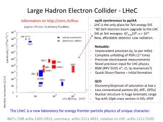
Overview of MEIC Electron Collider Ring. Yuhong Zhang. Electron Collider Ring Design Goals. A storage ring is capable of providing the following features Overall Electron energy 3 to 11 GeV

E N D
Overview of MEIC Electron Collider Ring Yuhong Zhang
Electron Collider Ring Design Goals • A storage ring is capable of providing the following features Overall • Electron energy 3 to 11 GeV • Accepting and accumulating full energy injected electron beam from CEBAF (No requirement of further upgrade of 12 GeV CEBAF) • Option of “top-off” current operation Geometric • Be large enough to accommodate 3 IPs (detectors) and all necessary components including RF system, spin manipulating, polarimetry, injection/ejection • Sharing a same (figure-8 shape) footprint with the ion collider ring of 60 (30) GeV/u protons (ions) Beam qualities • Be able to store a high average current (up to 3 A) and high bunch repetition rate (up to 1.5 GHz) CW electron beam • Be able to maintain a reasonable long beam life time • Small transverse emittance and short bunch length
Electron Collider Ring Design Goals (cont.) Polarization • high (>80%) polarization over a reasonable long period of time (>10 min) • Longitudinal spin direction at all interaction points • Capability of spin flipping beam • Be able to accommodate and self-polarizing positron beam Technical and cost-wise • Limiting synchrotron radiation power density below 20 kW/m, and also minimizing total radiation loss for requiring less RF power • Constructed with warm magnets Stability or operability • Achieving high stability & operability through modulation optics design • Consideration of beam control and diagnostics • Large momentum acceptance and dynamical aperture
Figure-8 Electron Collider Ring Footprint Ions from big booster Spin Rotator (8.8°/4.4°, 50 m) 1/4 Electron Arc (106.8°, 117.5 m) IR(60 m) IR(60 m) Spin Rotator (8.8°/4.4°, 50 m) Experimental Hall (radius 15 m) RF (20 m) Figure-8 crossing angle: 2x30° Spin Rotator (8.8°/4.4°, 50 m) Compton polarimeter (28 m) 1/4 Electron Arc (106.8°, 117.5 m) 3rd IR (60 m) Spin Rotator (8.8°/4.4°, 50 m) Injection from CEBAF
Formation of Stored Beam in the Collider Ring From CEBAF SRF Linac 0.67 ns (20 cm) 1.5 GHz < 3.3 ps (1 mm) 0.2 pC Microscopic bunch duty factor 5x10⁻³ 10-turn injection 33.3μs(2 pC) Stored beam in collider ring 40 ms (~5 damping times) 25 Hz Macroscopic bunch duty factor 8.5x10⁻³ 40 s • Full energy injection from CEBAF • 10-turn injection followed by phase space damping
More Topics • Electron collider ring optics design Alex Bogacz • RF systems for electron collider ring Haipeng Wang • Electron beam stability ByungYunn • Electron beam polarization VasiliyMorozov
Compton Polarimeter Layout chicane separates polarimetry from accelerator scattered electronmomentum analyzed in dipole magnet measured with Si or diamond strip detector pair spectrometer (counting mode) e+e– pair production in variable converter dipole magnet separates/analyzes e+ e– sampling calorimeter (integrating mode)count rate independent Insensitive to calorimeter response • Geometry: • Total dipole chicane length = 28 m • Dipoles = 3 m long, 2T • Electron beam deflection between dipoles 1-2 = 94 cm • scattered electron 6.7 cm (3.3 cm) from beam at endpoint at asymmetry zero crossing (green laser) • Photon detector 54 m from laser-electron interaction point David Gaskell