Download
1 / 30
300 likes | 306 Views
This text provides information about the design and implementation options of a large booster and collider ring for the Vasiliy Morozov MEIC Ion Complex. It discusses the layout, design considerations, and challenges related to the Full-Acceptance Detector IR Design. It also covers the compensation of 2nd-order terms and the geometry of the ion collider ring with the IR. Additionally, it presents the basic ring parameters and optics parameters.

E N D
Large Booster and Collider Ring Vasiliy Morozov MEIC Ion Complex Design Mini-Workshop, January 27, 2011
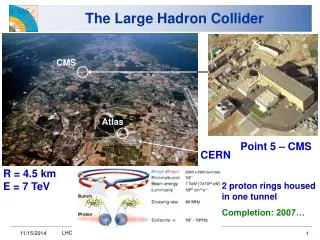
MEIC Layout Prebooster 0.2GeV/c 3-5 GeV/c protons Big booster 3-5GeV/c up to 20 GeV/c protons 3 Figure-8 rings stacked vertically
Big Booster • Acceleration of protons from 3-5 GeV/c to up to 20 GeV/c for injection into ion collider ring • Big booster implementation options • Separate warm ring in collider rings’ tunnel (current baseline) • Using the electron ring • Separate cold ring in the prebooster’s tunnel • Big booster design considerations • Avoid transition energy crossing • Space charge higher injection energy for larger ring • Matching RF systems debunch low-frequency beam and then rebunch it at higher frequency?
Figure-8 Collider Rings Ion Ring IP IP Siberian snake Siberian snake Potential IP Electron Ring IP IP RF RF Spin rotators Spin rotators Potential IP • Geometrical matching of electron and ion rings • Spin rotators in the electron ring • Siberian snakes in the proton ring arcs
Modular Design Concept • Design separately and incorporate/match into the ring • Vertical chicanes for stacking the ion ring arcs on top of the electron ring • Injection section • Electron cooling section • Siberian snakes • Interaction region with horizontal crossing • Section for local chromaticity compensation
IR Design Challenges • Low * is essential to MEIC’s high-luminosity concept • Large size of extended beam f * = F2 • Chromatic tune spread limited momentum aperture • Chromatic beam smear at IP F ~ Fp/p >> * limited luminosity • Sextupole compensation of chromatic effects limited dynamic aperture compensation of non-linear field effects • High sensitivity to position and field errors
Compensation of 2nd-Order Terms • Consider parallel beam after extension, u describes the dominant (cos-like) parallel component of the trajectory while is associated with the small remaining angular spread (sin-like trajectory), then, neglecting the angular divergence, one can approximate to obtain • In order to have the following conditions must be satisfied
Symmetry Concept • Modular approach: IR designed independently to be later integrated into ring • Dedicated Chromaticity Compensation Blocks symmetric around IP • Each CCB is designed to satisfy the following symmetry conditions • ux is anti-symmetric with respect to the center of the CCB • uy is symmetric • D is symmetric • n and ns are symmetric
Compensation of Main 2nd-Order Terms • 2nd-oder dispersion term and sextupole beam smear due to betatron beam size are automatically compensated. • Chromatic terms are compensated using sextupoles located in CCB’s attaining • local chromaticity compensation including contributions of both the final focusing quadrupoles and the whole ring • simultaneous (due to symmetry around IP) compensation of chromatic and sextupole beam smear at IP restoring luminosity
Ion Collider Ring Geometry with IR (I) • CCB’s on the opposite sides of IP bend the same way IP IP CCB CCB
Ion Collider Ring Geometry with IR (II) • CCB’s on the opposite sides of IP bend in the opposite directions • Simpler matching with electron IR’s, which have smaller bending IP IP IP IP
Ion Collider Ring Geometry with IR (III) IP IP IP IP 50
Arc FODO Cell • /3 betatron phase advance in both planes • Magnet parameters for 60 GeV/c protons: • Dipoles: • length = 3 m • bending radius = 53.8 m • bending angle = 3.2 • bending field = 3.7 T • Quads: • length = 0.5 m • strength = 92 T/m
Dispersion Suppressor • 3 arc quads are used to suppress dispersion while keeping -functions from growing • Maximum quad strength at 60 GeV/c = 122 T/m
Short Straight for Siberian Snake • Symmetric quad arrangement • Initial values from the dispersion suppressor • Quads varied to obtain x,y = 0 in the middle at limited max • Maximum quad strength at 60 GeV/c = 117 T/m
Arc End with Dispersion Suppression • Dispersion suppressed by varying quads with limitations on max and Dmax • Maximum quad strength at 60 GeV/c = 147 T/m To straight section
Complete Arc • Length = 381 m, net bend = 230, average radius = 95 m
Final Focusing Doublet • Distance from the IP to the first quad = 7 m • Maximum quad strength at 60 GeV/c = 175 T/m
Chromaticity Compensation Block • Satisfies the required symmetries for the orbital motion and dispersion • Maximum quad strength at 60 GeV/c = 78 T/m
Matching of CCB to Arc • Maximum quad strength at 60 GeV/c = 180 T/m
Matching of CCB to Straight • Maximum quad strength at 60 GeV/c = 180 T/m
Interaction Region • Total length = 143 m
Complete Collider Ring • Total length = 1353.75 m
Chromatic Tune Dependence • No compensation
Chromaticity Compensation • Two pairs of sextupoles placed symmetrically in each CCB • Maximum sextupole strength at 60 GeV/c = 519 T/m2
Chromatic Tune Dependence After compensation Before compensation