Download
1 / 12
120 likes | 259 Views
RF System for Electron Collider Ring. Haipeng Wang for the team of R. Rimmer and F. Marhauser, SRF Institute and Y. Zhang, G. Krafft and S. Derbenev, CASA. Medium Energy EIC Top Layout. Three compact rings: 3 to 11 GeV electron Up to 12 GeV/c proton (warm) Up to 60 GeV/c proton (cold).

E N D
RF System for Electron Collider Ring Haipeng Wang for the team of R. Rimmer and F. Marhauser, SRF Institute and Y. Zhang, G. Krafft and S. Derbenev, CASA
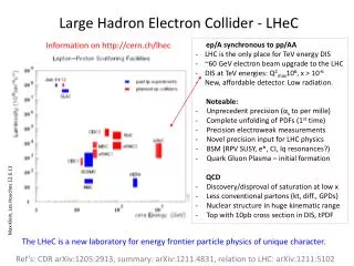
Medium Energy EIC Top Layout • Three compact rings: • 3 to 11 GeV electron • Up to 12 GeV/c proton (warm) • Up to 60 GeV/c proton (cold)
R=57.495 m 239.167 m MEIC collider ring 20.000 m 134.989 m 60° 379.609 m Electron collider ring figure 8 layout RF insertion Low energy High current High energy Low current 2
Electron Beam Stacking Structure for 5GeV 1.334 ns (40 cm) 0.750 GHz <3.3 ps (<1 mm) 0.4 pC From CEBAF SRF Linac Microscopic bunch duty factor 2.47x10⁻³ average current=0.3 mA 10-turn injection 33.3μs (4 pC) Stored beam in collider ring Macroscopic bunch duty factor 8.33x10⁻⁴ 40 ms (~5 times radiation damping) 25 Hz revolution time=3.33 μs, 2501 bunches per ring 40 s (1000 bunch trains), average current=3 A 3
Existing RF systems in storage rings: normal conducting Two examples Rimmer and Allen etc PEP-II BESSY Marhauser and Weihreter etc 4
Existing RF systems in storage rings: superconducting Two examples CESR-III B-cell Padamsee and Chojnacki etc KEKB-TRISTAN Furuya and Akai etc. 5
RF system in storage ring: Technology of choice Low RF Frequency Klystron power <600kW for CW RF power Beam loading control Power coupler and RF window High Current Low Energy Large beam aperture Bunch head-tail instability Synchrotron radiation power Beam excited HOMs RF acceleration High Energy Low Current ceramics Low broadband and narrow band HOM impedance cavity Warm HOM windows and loads HOM damping by waveguide or coaxial coupler ferrites Normal conducting cavity Superconducting cavity Low gradient for CW High gradient for CW DI water cooling <300K Liquid helium Cooling, 4.2K 6
Scaled RF system for MEIC Electron ring: normal conducting 11GeV 5GeV Marhauser and Weihreter BESSY: <100kW Eacc=6MV/m Conditioned up to 30kW CW in 5 days. 7
Scaled RF system for MEIC electron ring: superconducting Only single-cell is preferred due to a heavy HOM damping requirement in storage ring, But space is limited. 11GeV 5GeV JLab High Current 750MHz, 5-cell, 1A cavity Rimmer and Wang etc 8
Initial HOM Analysis: beam current excitation S. H. Kim and H.Wang FFT • Time averaged HOM power normalized to R/Q (W/W= Amp2) is current square drive term. It has no information of the cavity but with assumed HOM damping Qext. • For example, if we have a HOM resonated at 2.25GHz with R/Q of 10 W and Q external of 100 , we have 1kW HOM power from the beam in this mode. • When we design a high current cavity, we have to avoid HOM frequencies sitting on the beam excitation resonances. • H. Wang etc PAC2005 TPPT086. 9
Initial HOM damping analysis: Impedance and HOM power BESSY CWCT copper cavity impedance measurement s Marhauser and Weihreter, EPAC 2004 • Impedance scaling from BESSY • NC RF cavity in same shape but in different frequency scale: • monopole modes around 2.25 GHz have to be avoid by either changing the cavity shape (safe to park) or damping totally with Qext< 100, otherwise 50kW (on resonance HOM power will come out to the HOM loads. • Following is an example (H. Wang etc PAC 2005) for JLab High Current 5-cell cavity design to avoid HOM resonance by choosing different cavity shapes. 10
MEIC electron ring RF system Summary: Pros and Cons NCRF favors to Low Energy, High Current Operation SCRF favors to High Energy, Low Current Operation 11