Download
1 / 28
280 likes | 503 Views
Conceptual Design of High Luminosity Ring-Ring Electron-Ion Collider at CEBAF. Yuhong Zhang For ELIC Design Group HB2008 August 26, 2008. Outline. Science Motivation Design Goals ELIC Conceptual Design Layout and Parameter Set Figure-8 Ring Interaction Region

E N D
Conceptual Design of High Luminosity Ring-Ring Electron-Ion Collider at CEBAF Yuhong Zhang For ELIC Design Group HB2008 August 26, 2008
Outline • Science Motivation • Design Goals • ELIC Conceptual Design • Layout and Parameter Set • Figure-8 Ring • Interaction Region • R&D Requirements and Advances • Summary
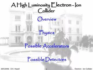
Science Motivation A High Luminosity, High Energy Electron-Ion Collider: A New Experimental Quest to Study the Glue which Binds Us All How do we understand the visible matter in our universe in terms of the fundamental quarks and gluons of QCD? Explore the new QCD frontier: strong color fields in nuclei • How do the gluons contribute to the structure of the nucleus? • What are the properties of high density gluon matter? • How do fast quarks or gluons interact as they traverse nuclear matter? Precisely image the sea-quarks and gluons in the nucleon • How do the gluons & sea-quarks contribute to spin structure of the nucleon? • What is the spatial distribution of the gluons and sea quarks in the nucleon? • How do hadronic final-states form in QCD?
Energy • e: 3 GeV to ≥ 10 GeV • P: 25 GeV to 250 GeV • A: 20 GeV to 100 GeV • Ion species • up to gold, A ≥ 197 • Luminosity • ≥ 10 x 3.8·1031 cm-2s-1 • Polarization • electron beam • light ion beams EIC Requirements from NSAC LRP 2007 “… These considerations constrain the basic design parameters to be a 3 to at least 10 GeV energy electron colliding with a nucleon beam of energy between 25 to 250 GeV or with nuclear beams ranging from 20 to 100 GeV/nucleon” “… the performances needed at an EIC relies on three major advances over HERA: (1) beams of heavy nuclei, at least up to gold, are essential at access the gluon saturation regime … (2) collision rates exceeding those at HERA by at leasttwo orders of magnitude are required for precise and definitive measurements of the gluon distributions of interest, … and (3) polarized light-ion beams, in addition to polarized electrons available at HEAR, are mandatory to address central question of the nucleon’s spin structure in the gluon-dominated region”
ELIC Design Goals • Energy • Center-of-mass energy between 20 GeV and 100 GeV • energy asymmetry of ~ 10, 3 GeV electron on 30 GeV proton/15 GeV/n ion up to 10 GeV electron on 250 GeV proton/125 GeV/n ion • Luminosity • 1033 up to 1035 cm-2 s-1per interaction point • Ion Species • Polarized H, D, 3He, possibly Li • Up to heavy ion A = 208, all striped • Polarization • Longitudinal polarization at the IP for both beams • Transverse polarization of ions • Spin-flip of both beams • All polarizations >70% desirable • Positron Beamdesirable
ELIC Conceptual Design Accumulator-cooler ring & prebooster 30-250 GeV protons 15-125 GeV/n ions (Large booster) 12 GeV CEBAF Upgrade Green-field design of ion complex directly aimed at full exploitation of science program. 3-10 GeV electrons 3-10 GeV positrons
Achieving High Luminosity of ELIC ELIC design luminosity L~ 8.6 x 1034 cm-2 sec-2 (250 GeV protons x 10 GeV electrons) ELIC luminosity Concepts • High bunch collision frequency (up to 1.5 GHz) • Short ion bunches (σz ~ 5 mm) • Super strong final focusing (β* ~ 5 mm) • Large beam-beam parameters (0.01/0.01 per IP, 0.025/0.1 largest achieved) • Need High energy electron cooling of ion beams • Need crab crossing colliding beams • Large synchrotron tunes to suppress synch-betatron resonances • Equal betatron phase advance (fractional) between IPs
ELIC (e/A) Design Parameters • Luminosity is given per unclean per IP • 499 MHz bunch collision frequency
Evolutionof ELIC Conceptual Design • Energy Recovery Linac-Storage-Ring (ERL-R) • ERL with Circulator Ring-Storage-Ring (CR-R) • Storage-Ring- Storage-Ring (R-R) (by taking advantages of CEBAF high bunch repetition frequency and a green field design of ion complex) • Challenge: high current polarized electron beam • ERL: 2 A • Circulator ring: 20 mA • State-of-art: 0.1 mA • 12 GeV CEBAF Upgrade polarized source/injector already meets beam requirement of ring-ring design • 12 GeV CEBAF will serve as full energy polarized injector to the ring • ELIC ring-ring design still preserves high luminosity, high polarization
ELIC Ring-Ring Design Features • Unprecedented high luminosity • Enabled by short ion bunches, low β*, high rep. rate, large synchrotron tune • Require crab crossing colliding beam • Electron cooling is an essential part of ELIC • Four IPs (detectors) for high science productivity • “Figure-8” ion and lepton storage rings • Ensure spin preservation and ease of spin manipulation • No spin sensitivity to energy for all species. • Present CEBAF gun/injector meets electron storage-ring requirements • The 12 GeV CEBAF can serve as a full energy injector to electron ring • Simultaneous operation of collider and CEBAF fixed target program. • Experiments with polarized positron beam are possible.
Figure-8 Ring Footprint 20000 z [cm] 10000 186 m 372 m 90 deg x [cm] 0 -40000 -30000 -20000 -10000 0 10000 20000 30000 40000 -10000 -20000 Interaction Point Ion ring Vertical crossing electron ring Figure-8 Ring • Design is determined by • Synchrotron radiation power & density • Arc bending magnet strength • Length of crossing straights • Cost and fit to site Stacked vertically
920 m 360 m ELIC at JLab Site WM Symantac City of NN VA State City of NN SURA JLab/DOE
straight section (372 m) Note: dimension of the drawing not to scale 106 m 106 m 35 m 35 m spin rotator spin rotator e vertical bend vertical bend e 35 m 35 m 0.75 m arc bend arc dipoles 20 m i collision point collision point i 0.75 m Vertical crossing angle (27 mrad) spin rotators vertical bend vertical bend Minimizing crossing angle reduces crab cavity challenges & required R&D 35 m 35 m 20 m 35 m 35 m 106 m 106 m y Interaction Region z 70 m IP FODO Chrom Chrom FF FF FODO Matching quads Matching quad Crab cavity Crab cavity 6 m Figure-8 Straight Sections and IPs • 106 m space to accommodate e/p injection/ejection, SRF cavity, e-cooling, and polarimetry
0.5m 3.2kG/cm 0.2m 27 mrad 1.27 deg 3m 0.6m 2.55kG/cm 8.4cm 10cm IP 1.8m 20.8kG/cm 22.9cm 3m 12KG/cm Vertical intercept Vertical intercept 14.4cm 16.2cm 3.7m Vertical intercept electron 4mm 5mm ion IR Layout and Beam Envelopes Detector space • Magnet free space (for detector) is +/- 3 m • Final focusing achieved by quad doublet for both beams • 250 T/m peak field gradient (7.5 T over 3 cm aperture radius) • Electron & ion doublets “Interleave” to avoid physical magnet overlap • Quad design calls for a “pass through” hole through a magnet yoke • Chromatic aberration compensation by two families of sextupoles
ELIC R&D Requirements To achieve luminosity at 1033 cm-2 sec-1 and up • High energy electron cooling To achieve luminosity at ~ 1035 cm-2 sec-1 • Crab crossing and crab cavity • Forming and stability of intense ion beams • Beam-beam interactions • Detector R&D for high repetition rate (>0.5 GHz) • What is the problem? • How does it affect the ELIC design? • How these R&D topics are selected and prioritized? • What is our approach to these topics?
ELIC R&D: Electron Cooling Issue • To suppress IBS, reduce emittances, provide short ion bunches. • Effective for heavy ions (higher cooling rate), difficult for protons. State-of-Art • Fermilab demonstration (4.34MeV, 0.5A DC) • Feasibility of EC with bunched beams remains to be demonstrated. ELIC ERL Based Circulator Cooler • 2 A CW electron beam, up to 137 MeV • Non-polarized electron source (present or under developing) can deliver nC bunch • SRF ERL able to provide high average current CW beam • Circulator cooler for reducing average current from source/ERL • Electron bunches circulate 100 times in a ring while cooling ion beam
Cooling Time and Ion Equilibrium • Multi-stage cooling scenario in the collider ring • 1st stage: longitudinal cooling with SRF bunching at injection energy • 2nd stage: initial cooling after acceleration to top energy • 3rd stage: continuous cooling in collider mode Cooling rates and equilibrium of proton beam * max.amplitude ** norm.,rms
ELIC R&D: Crab Crossing • High repetition rate requires crab crossing colliding beam to avoid parasitic beam-beam interaction • Crab cavities needed to restore head-on collision & avoid luminosity reduction • Minimizing crossing angle reduces crab cavity challenges & required R&D State-of-art: KEKB Squashed cell@TM110 Mode Crossing angle = 2 x 11 mrad Vkick=1.4 MV, Esp= 21 MV/m
ELIC R&D: Crab Crossing(cont.) ELIC Crab cavity Requirements (Based on 27 mrad crossing angle) Electron: 1.5 MV – within state of art (KEK, single Cell, 1.8 MV) Ion: 30 MV (220G/4m integrated B field on axis) Crab Crossing R&D program • Cavity development • Understand gradient limit and packing factor • Multi-cell SRF crab cavity design capable for high current operation. • Phase and amplitude stability requirements • Beam dynamics study with crab crossing • Effect on collider luminosity • Effect on synchrotron-betatron motion and instability
ELIC R&D: Forming High Intensity Ion Beam Stacking/accumulation process • Multi-turn (~20) pulse injection from SRF linac into an accumulator-cooler ring • Damping/cooling of injected beam • Accumulation of 1 A coasted beam at space charge limited emittence • Fill prebooster/large booster, then acceleration • Switch to collider ring for energy booster, RF bunching and initial/continuous cooing Stacking proton beam in ACR
Electron bunch IP Proton bunch Electron bunch proton bunch y x ELIC R&D: Beam-Beam Interaction Transvers beam-beam force • Highly nonlinear forces • Produce transverse kickers between colliding bunches Beam-beam effect • Can cause emittance growth or blowup • Can induce coherent beam-beam instabilities • Can decrease luminosity and its lifetime Most important limiting factor of collider luminosity ! Impact on ELIC IP design • Highly asymmetric colliding beams (10 GeV/1.65 A on 250 GeV/0.66 A) • Four IPs and Figure-8 rings • Strong final focusing (beta* 5 mm) • Short bunch length (5 mm) • Crab crossing colliding beam • Large synchrotron tune required by RF bunching • Near-limit vertical b-b parameters (0.1/0.01) • Equal (fractional part) betratron phase advance between IPs One slice from each of opposite beams Beam-beam force
ELIC R&D: Beam-Beam (cont.) Simulation Model • Single/multiple collision points, head-on collision • Strong-strong self-consistent Particle-in-Cell codes • Ideal rings for electrons & protons, but include synchrotron radiation damping & quantum excitations for electrons Scope and Limitations • 20k turns (0.15s of storing time) for a typical simulation run • Reveals short-time dynamics with accuracy • Can’t predict long term (>min) dynamics Simulation results • Single IP case Reach equilibrium luminosity, 6.1·1034 cm-2s-1, after one damping time, loss mainly due to the hour-glass effect • Parameter dependence of ELIC luminosity Coherent beam-beam instabilities and emittance blow-up observed at electron beam above 6.5 A, however away from ELIC design point • 4 IP with two sets of 12 bunches Reach equilibrium luminosity 5.9·1034 cm-2s-1, after one damping time It is the first phase of a long-term research plan
Summary ELIC Conceptual Design provides • CM energy up to 100 GeV, light to heavy ions (A=208) • Unprecedented high luminosity (up to 2.9·1034 cm-2 s-1 @499MHz or 8.6·1034 cm-2 s-1 @1497MHz, for e-p) • High polarization for both electron & light ion beams • Simultaneous operation of collider and CEBAF fixed target program • Design evolution towards more robust • Increase using existed and proved technologies • Reduces technology challenges and required R&D effort Recent R&D Advances • Complete ring and IP beam optics with chromaticity correction • Electron cooling and circulator cooler conceptual design • Crab crossing and crab cavity scheme • Forming and instability studies of intense ion beam • Beam-beam effects Continue design optimization and carry out key R&D
ELIC Study Group & Collaborators A. Afanasev, E. Aschenauer, J. Benesch, A. Bogacz, P. Brindza, A. Bruell, L. Cardman, Y. Chao, S. Chattopadhyay, P. Chevtsov, E. Chudakov, P. Degtiarenko, J. Delayen, Ya. Derbenev, R. Ent, P. Evtushenko, A. Freyberger, D. Gaskell, J. Grames, A. Hutton, R. Kazimi, G. Krafft, R. Li, L. Merminga, J. Musson, M. Poelker, R. Rimmer, A. Thomas, H. Wang, C. Weiss, B. Wojtsekhowski, B. Yunn, Y. Zhang - Jefferson Laboratory W. Fischer, C. Montag - Brookhaven National Laboratory V. Danilov - Oak Ridge National Laboratory V. Dudnikov - Brookhaven Technology Group P. Ostroumov - Argonne National Laboratory V. Derenchuk - Indiana University Cyclotron Facility A. Belov - Institute of Nuclear Research, Moscow, Russia V. Shemelin - Cornell University D. Barber, DESY
spin rotator with 90º solenoid snake spin rotator spin rotator collision point collision point collision point collision point spin rotator with 90º solenoid snake spin rotator spin rotator Electron Polarization in ELIC • Producing polarization at CEBAF • Polarized source, preserved in acceleration at CEBAF recirculated linac • Injected into Figure-8 ring with vertical polarization • Maintaining polarization in the ring • Equilibrium polarization in the ring determined by • Sokolov-Ternov self-polarization • Depolarization (quantum, vertical betatron oscillation, orbit distortion and beam-beam interaction) • SC solenoids at IPs removes spin resonances and energy sensitivity
spin spin rotator spin rotator spin tune solenoid e Spin tune solenoid e collision point i collision point i 90º 90º spin tune solenoid spin tune solenoid snake solenoid Electron Polarization in ELIC (cont.) • Polarization manipulation • Vertical polarization in arc, but longitudinal at IP required by physics • Use vertical crossing bend to rotate spin, but energy-dependent • Combination of vertical crossing bend, two arc bending dipoles and two superconducting solenoids for energy independent spin rotation • 180° snake solenoid & symmetry principle ensure longitudinal polarization at 2nd IP & vertical polarization in the other arc of Figure-8 ring