Download
1 / 34
350 likes | 510 Views
Semiconductors. computers air bags Palm pilots cell phones pagers DVD players TV remotes satellites fiber networks switches photocells Peltier refrigerators thermoelectric generators lasers aerospace electronics

E N D
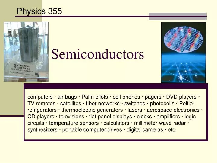
Semiconductors computers air bags Palm pilots cell phones pagers DVD players TV remotes satellites fiber networks switches photocells Peltier refrigerators thermoelectric generators lasers aerospace electronics CD players televisions flat panel displays clocks amplifiers logic circuits temperature sensors calculators millimeter-wave radar synthesizers portable computer drives digital cameras etc. Physics 355
Diamond • In the diamond structure, the carbon atoms are arranged on an fcc-type lattice with a total of 16 electrons per primitive cell. • The valence band and 7 lower bands are full, leaving no electrons in the conduction band.
Diamond Electrons may be thermally activated to jump a gap. At room temperature, kBT is only 0.026 eV. To jump the energy gap, the electron requires very high temperatures. So, diamond is an excellent insulator. ρ = 1018-m
Graphite ρ = 9 -m
Silicon • Silicon has the diamond structure. • There are 14 electrons per primitive cell. • Gap is only 1.12 eV, however. Now there is a small (but finite) chance for a few electrons to be thermally excited from valence band to conduction band.
Effective Mass Revisited • An electron moving in the solid under the influence of the crystal potential is subjected to an electric field. • We expect an external field to accelerate the electron, increasing E and k and change the electron’s state.
Effective Mass Revisited eE = F
Effective Mass Revisited • This relates the curvature of the band to the “effective mass.” • One can show that a free electron “band” gives an effective mass equal to the rest mass of an electron. • Electrons in a crystal are accelerated in response to an external force just as though they were free electrons with effective mass me. • Usually , me < m0.
Effective Mass Revisited in multiples of the free electron mass m0 = 9.11 1031 kg
Experimental Measurement • Traditionally effective masses were measured using cyclotron resonance, a method in which microwave absorption of a semiconductor immersed in a magnetic field goes through a sharp peak when the microwave frequency equals the cyclotron frequency. • In recent years effective masses have more commonly been determined through measurement of band structures using techniques such as angle-resolved photoemission or, most directly, the de Haas-van Alphen effect. • Effective masses can also be estimated using the coefficient g of the linear term in the low-temperature electronic specific heat at constant volume Cv. The specific heat depends on the effective mass through the density of states at the Fermi level and as such is a measure of degeneracy as well as band curvature.
Electrons & Holes For the electrons occupying the vacant states, (Negative!) and the electrons will move in same direction as electric field (wrong way!) • In a semiconductor, there are two charge carriers: • Electrons (conduction band) • negative mass • negative charge • Holes (valence band) • positive mass, • positive charge
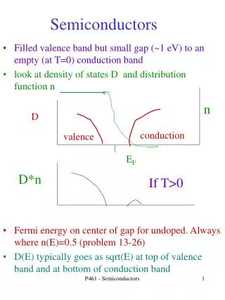
Carrier Concentration To calculate the carrier concentrations in energy bands we need to know the following parameters: • The distribution of energy states or levels as a function of energy within the energy band, D(). • The probability of each of these states being occupied by an electron, f(). Electron Density Hole Density
A band is shown for a one-dimensional crystal. The square represents an initially empty state in an otherwise filled band. When an electric field is applied, the states represented by arrows successsively become empty as electrons make transitions.
The band is completely filled except for a state marked by a square. Except for the electron represented as a circle, each electron can be paired with another, so the sum of their crystal momentum vanishes. The total crystal momentum for the band and the crystal momentum of the hole are both ħk.
The empty state and the unpaired electron for two times are shown when an electric field is applied. The change in momentum is in the direction of the field.
Conduction Band Carrier Concentration For >> F, the Boltzmann distribution approximates the F-D distribution: which is valid for the tail end of the distribution.
Conduction Band Carrier Concentration Effective Density of States for the Conduction Band
Valence Band Carrier Concentration • The hole distribution is related to the electron distribution, since a hole is the absence of an electron. • The holes near the top of the valence band behave like particles with effective mass mh; and the density of states is
Equilibrium Relation • Multiply n and p together: • The product is constant at a given temperature. • It is also independent of any impurity concentration at a given temperature. This is because any impurity that adds electrons, necessarily fills holes. • This is important in practice, since we could reduce the total carrier concentration n + p in an impure crystal via the controlled introduction of suitable impurities – such reduction is called compensation.
c F v Intrinsic Semiconductors
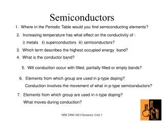
Extrinsic Semiconductors • Extrinsic semiconductors: we can add impurities to make a material semiconducting (or to change the properties of the gap). • There are 2 types of extrinsic semiconductors: p-type andn-type • These are materials which have mostly hole carriers (p) or electron carriers (n). • These give you ways of modifying the band gap energies (important for electronics, detectors, etc).
Extrinsic Semiconductors: n type • Add a small amount of phosporus (P: 3s23p3) to Silicon (Si: 3s23p2) (generally, a group V element to a group IV host) P replaces a Si atom and it donates an electron to the conduction band (P is called the donor atom). The periodic potential is disrupted and we get a localized energy level, D. • This is an n-type semiconductor – more electrons around that can be mobile; and the Fermi energy is closer to the conduction band.
Extrinsic Semiconductors: n type Phosphorus provides an extra electron. C – D = 45 meV So, its easy for the donor electrons to enter the conduction band at room temperature. This means that at room temperature n » ND. This is called complete ionization (only true if ni << ND). Therefore, by doping Si crystal with phosphorus, we increase the free electron concentration. At low temperature, these extra electrons get trapped at the donor sites (no longer very mobile) - the dopant is frozen out.
c F A v Extrinsic Semiconductors: p type • Next suppose Si atom is replaced with Boron (B: 2s22p) to Silicon (Si: 3s23p2). Again, we have a perturbed lattice and a localized E-level created. • Boron is missing an electron and accepts an electron from valence band, creating a hole. • Therefore doping with B increases hole concentration. We call this p-type doping, the electron concentration n is reduced. • F moves closer to V.
Extrinsic Semiconductors Boron in Silicon
Mass Action Law • Valid for both intrinsic and extrinsic semiconductors. • It is important in devices to control n and p concentrations and to suppress the influence of the intrinsic concentration. • These equations are important in establishing upper limits in semiconductor operating temperature. • We generally require ni<< (minimum doping density) and, practically, this means we need doping concentrations above 1014 cm3.