Download
1 / 28
350 likes | 839 Views
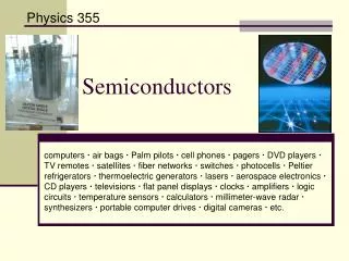
Semiconductors. Semiconductors. A Semiconductor is a material whose resistivity is between that of a good conductor and a good insulator . Examples of materials which are semiconductors are Silicon and Germanium. Semiconductors.

E N D
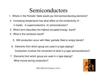
Semiconductors • A Semiconductor is a material whose resistivity is between that of a good conductor and a good insulator. • Examples of materials which are semiconductors are Silicon and Germanium.
Semiconductors • The resistance of a semiconductor decreases as its temperature increases • This is because as the temperature of the material increases it heats up, releasing many electrons from their atoms. • These electrons are now available for conduction and so resistance decreases. • This ‘liberation’ of electrons can also be caused by light shining on the material
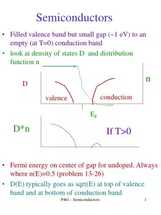
Conduction Electrons • As the pure semiconductor heats up some of the valance electrons are given enough energy to break free from there covalent bond and become conduction elections. • These are called negative electrons
Hole • The ‘gap’ that is left when the electron breaks free from its bond are often referred to as ‘positive holes’ because the atom has become positively charges since it has lost an electron.
Intrinsic Conduction • Intrinsic Conduction is the movement of charges through a pure semiconductor. • During intrinsic conduction there are equal amounts of negative electrons moving from negative to positive as positive holes moving in the opposite direction. • The current is small and depends on the temperature of the semiconductor.
Explanation: • Current increases with increasing voltage. • The slope of the graph increases, showing that as the voltage increases the resistance decreases. This is because as the voltage increases so does the current, this heats the semiconductor which causes more electrons to be freed for conduction, thus lowering resistance.
Extrinsic Conduction • Extrinsic Conduction is the movement of charges through a doped semiconductor. Doping • Doping is the addition of a small amount of atoms of another element to a pure semiconductor to increase its conductivity.
N-type semiconductor • An impurity is added produces more free electrons available for conduction. • A group V element is added. • Negative elections are the majority charge carrier, holes the minority carrier. • In this case there is one ‘extra’ electron due to the addition of the Phosphorus atom.
P-type semiconductor • A P-type semiconductor is a semiconductor in which holes are the majority charge carriers. • In this case there is one ‘missing’ electron due to the addition of a group III element ieBoron atom. This is equivalent to a ‘Positive Hole’ which moves in the opposite direction to an electron.
Semiconductor Devices • The operation of semiconductor devices depends on the effects that occur when p-type and n-type semiconductor material are in close contact. This is achieved by taking a single crystal of silicon and doping separate but adjacent layers of it with suitable impurities. The junction between the p-type and the n-type layers is referred to as the p–n junction. • Devices such as diodes, transistors, silicon-controlled rectifiers, etc., all contain one or more p–n junctions.
The p-n junction • When a piece of p-type semiconductor is joined to a piece of n-type semiconductor, the junction between the two is known as a p-n junction.
The Depletion Region • The depletion region is so named because it is formed from a conducting region of the semiconductor which has been depleted of all free charge carriers, leaving none to carry a current. • Understanding the depletion region is key to explaining modern semiconductor electronics in action.
Due to thermal agitation, some free electrons in the n-type material diffuse over to the p-type material, where they combine with nearby positive holes, with the result that the region is depleted of two of its charge carriers. • Similarly on the p-type side some positive holes diffuse over to the n-type material, where they too combine with nearby electrons, with the result that the region gets depleted of two more of its charge carriers.
The end result is that a depletion region is formed at the junction of the p-type and n-type materials, where there are no free charge carriers. This region therefore acts as an insulator.
Work now needs to be done to bring charge from one side of this depletion region to the other; therefore a potential difference (voltage) exists across the region. • This voltage is typically about 0.1 volts for a germanium diode, and 0.6 volts for a silicon diode. • This voltage is known as the junction voltage.
Current flow across a p-n junction Forward-biased p-n junction • Here the positive terminal of the junction is connected to the p-type and the negative terminal is connected to the n-type. • Electrons in the N-type area above are repelled from the negative terminal and drive in to the depletion region. • Similarly positive holes in the P-type are repelled from the positive terminal and drive into the depletion region from the other side.
The end result is that the width of the depletion layer is reduced. • In fact if the voltage across the terminals is sufficiently great (greater than what is known as the junction voltage) the depletion layer is completely broken down and the region now becomes a conductor.
Reversed-biased p-n junction • Here the positive terminal of the junction is connected to the n-type and the negative terminal is connected to the p-type. • Electrons in the N-type area above are now attracted to the positive terminal and because as a result the depletion region in this section grows bigger.
Similarly positive holes in the P-type are attracted to the negative terminal. • The end result is that the width of the depletion layer is increased. • The end result is that no charges actually move through the depletion region and it remains an insulator.
Applications of the p-n junction • The p-n junction is the principle behind the semiconductor diode, which lies at the heart of most electronic systems, including LEDs, computers and integrated circuits. • It is also responsible for rectification of a.c. (converting a.c. to d.c.).
A (semiconductor) diode will only allow current to flow in one direction.
Thermistor • A Thermistor is an electrical component whose resistance decreases rapidly with increasing temperature.
Light Dependant Resistor • A Light Dependant Resistor (LDR) is an electrical component whose resistance decreases rapidly when light shines on it.