Download

1 / 24
260 likes | 824 Views
SEMICONDUCTORS. Semiconductors Semiconductor devices. Electronic Properties Robert M Rose, Lawrence A Shepart, John Wulff Wiley Eastern Limited, New Delhi (1987). Energy gap in solids. In the free electron theory a constant potential was assumed inside the solid

E N D
SEMICONDUCTORS • Semiconductors • Semiconductor devices Electronic Properties Robert M Rose, Lawrence A Shepart, John Wulff Wiley Eastern Limited, New Delhi (1987)
Energy gap in solids • In the free electron theory a constant potential was assumed inside the solid • In reality the presence of the positive ion cores gives rise to a varying potential field • The travelling electron wave interacts with this periodic potential (for a crystalline solid) • The electron wave can be Bragg diffracted
Bragg diffraction from a 1D solid 1D =90o n = 2d Sin n = 2d • The Velocity of electrons for the above values of k are zero • These values of k and the corresponding E are forbidden in the solid • The waveform of the electron wave is two standing waves • The standing waves have a periodic variation in amplitude and hence the electron probability density in the crystal • The potential energy of the electron becomes a function of its position(cannot be assumed to be constant (and zero) as was done in the free electron model)
k→ E → Band gap
The magnitude of the Energy gap between two bands is the difference in the potential energy of two electron locations K.E of the electron increasingDecreasing velocity of the electronve effective mass (m*) of the electron Within a band E → k→
Effective energy gap → Forbidden gap → Band gap [110] [100] Effective gap E → E → k→ k→
The effective gap for all directions of motion is called the forbidden gap • There is no forbidden gap if the maximum of a band for one direction of motion is higher than the minimum for the higher band for another direction of motion this happens if the potential energy of the electron is not a strong function of the position in the crystal
Energy band diagram: METALS Divalent metals Monovalent metals • Monovalent metals: Ag, Cu, Au → 1 e in the outermost orbital outermost energy band is only half filled • Divalent metals: Mg, Be → overlapping conduction and valence bands they conduct even if the valence band is full • Trivalent metals: Al → similar to monovalent metals!!! outermost energy band is only half filled !!!
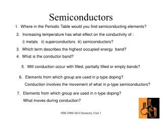
Energy band diagram: SEMICONDUCTORS 2-3 eV • Elements of the 4th column (C, Si, Ge, Sn, Pb) → valence band full but no overlap of valence and conduction bands • Diamond → PE as strong function of the position in the crystal Band gap is 5.4 eV • Down the 4th column the outermost orbital is farther away from the nucleus and less bound the electron is less strong a function of the position in the crystal reducing band gap down the column
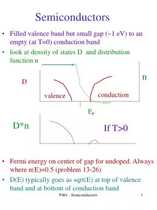
Intrinsic semiconductors • At zero K very high field strengths (~ 1010 V/m) are required to move an electron from the top of the valence band to the bottom of the conduction band • Thermal excitation is an easier route P(E) → E → Eg Eg/2
T > 0 K Unity in denominator can be ignored • ne→ Number of electrons promoted across the gap (= no. of holes in the valence band) • N → Number of electrons available at the top of the valance band for excitation
Conduction in an intrinsic semiconductor • Under applied field the electrons (thermally excited into the conduction band) can move using the vacant sites in the conduction band • Holes move in the opposite direction in the valence band • The conductivity of a semiconductor depends on the concentration of these charge carriers (ne& nh) • Similar to drift velocity of electrons under an applied field in metals in semiconductors the concept of mobility is used to calculate conductivity
Conductivity as a function of temperature Ln()→ 1/T (/K) →
Extrinsic semiconductors • The addition of doping elements significantly increases the conductivity of a semiconductor • Doping of Si V column element (P, As, Sb)→ the extra unbonded electron is practically free (with a radius of motion of ~ 80 Å) Energy level near the conduction band n- type semiconductor III column element (Al, Ga, In)→ the extra electron for bonding supplied by a neighbouring Si atom → leaves a hole in Si. Energy level near the valence band p- type semiconductor
Ionization Energy→Energy required to promote an electron from the Donor level to conduction band • EIonization < Eg even at RT large fraction of the donor electrons are exited into the conduction band n-type EIonization Eg Donor level • Electrons in the conduction band are the majority charge carriers • The fraction of the donor level electrons excited into the conduction band is much larger than the number of electrons excited from the valence band • Law of mass action:(ne)conduction band x (nh)valence band = Constant • The number of holes is very small in an n-type semiconductor • Number of electrons ≠ Number of holes
p-type Acceptor level Eg EIonization • At zero K the holes are bound to the dopant atom • As T↑ the holes gain thermal energy and break away from the dopant atom available for conduction • The level of the bound holes are called the acceptor level (which can accept and electron) and acceptor level is close to the valance band • Holes are the majority charge carriers • Intrinsically excited electrons are small in number • Number of electrons ≠ Number of holes
Intrinsic slope All dopant atoms have been excited Exhaustion Exponentialfunction (/ Ohm / K)→ Extrinsic +ve slope due to Temperature dependentmobility term Slope can be usedfor the calculationof EIonization 0.1 0.06 0.08 0.02 0.04 50 K 10 K 1/T (/K) →
Semiconductor device chose the flat region where the conductivity does not change much with temperature • Thermistor (for measuring temperature) maximum sensitivity is required