Download
1 / 16
180 likes | 370 Views
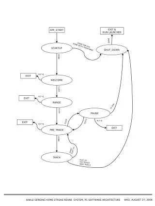
PC System Architecture PCIe Interconnect. Lecture 25. Bandwidth – Gravity Computer Systems. The Bandwidth between key components ultimately dictates system performance Especially true for massively parallel systems processing massive amount of data

E N D
PC System ArchitecturePCIe Interconnect Lecture 25
Bandwidth – Gravity Computer Systems • The Bandwidth between key components ultimately dictates system performance • Especially true for massively parallel systems processing massive amount of data • Tricks like buffering, reordering, caching can temporarily defy the rules in some cases • Ultimately, the performance falls back to what the “speeds and feeds” dictate
Classic PC architecture CPU • Northbridge connects 3 components that must be communicate at high speed • CPU, DRAM, video • Video also needs to have 1st-class access to DRAM • Video/graphicscards are connected to Accelerated graphics Port (AGP), up to 2 GB/s transfers • Southbridge serves as a concentrator for slower I/O devices Core Logic Chipset
(Original) PCI Bus Specification • Connection through the southBridge • Originally 33 MHz, 32-bit wide, 132 MB/second peak transfer rate • More recently 66 MHz, 64-bit, 528 MB/second peak • Upstream bandwidth remain slow for device (~256MB/s peak) • Shared bus with arbitration • Winner of arbitration becomes bus master and can connect to CPU or DRAM through the southbridge and northbridge
PCI as Memory Mapped I/O • PCI device registers are mapped into the CPU’s physical address space • Accessed through loads/ stores (kernel mode) • Can use I/O registers as data structures in programming languages • Addresses are assigned to the PCI devices at boot time • All devices listen for their addresses
PCI Express (PCIe) • Switched, point-to-point connection • Each card has a dedicated “link” to the central switch, no bus arbitration. • Packet switches messages form virtual channel • Prioritized packets for QoS • E.g., real-time video streaming
PCIe 2 Links and Lanes • Each link consists of one or more lanes • Each lane is 1-bit wide (4 wires, each 2-wire pair can transmit 2.5Gb/s in one direction) • Upstream and downstream now simultaneous and symmetric • Each Link can combine 1, 2, 4, 8, 12, 16 lanes- x1, x2, etc. • Each byte data is 8b/10b encoded into 10 bits with equal number of 1’s and 0’s; net data rate 2 Gb/s per lane each way. • Thus, the net data rates are 250 MB/s (x1) 500 MB/s (x2), 1GB/s (x4), 2 GB/s (x8), 4 GB/s (x16), each way
8/10 bit encoding • Goal is to maintain DC balance while have sufficient state transition for clock recovery • The difference of 1s and 0s in a 20-bit stream should be ≤ 2 • There should be no more than 5 consecutive 1s or 0s in any stream • 00000000, 00000111, 11000001 bad • 01010101, 11001100 good • Find 256 good patterns among 1024 total patterns of 10 bits to encode an 8-bit data • An 20% overhead
PCIe PC Architecture • PCIe forms the interconnect backbone • Northbridge/Southbridge are both PCIe switches • Some Southbridge designs have built-in PCI-PCIe bridge to allow old PCI cards • Some PCIe I/O cards are PCI cards with a PCI-PCIe bridge • Source: Jon Stokes, PCI Express: An Overview • http://arstechnica.com/articles/paedia/hardware/pcie.ars
GeForce 7800 GTXBoard Details SLI Connector Single slot cooling sVideo TV Out DVI x 2 • 256MB/256-bit DDR3 • 600 MHz • 8 pieces of 8Mx32 16x PCI-Express
PCIe 3 • A total of 8 Giga Transfers per second in each direction • No more 8/10 encoding but uses a polynomial transformation at the transmitter and its inverse at the receiver to achieve the same effect • So the effective bandwidth is double of PCIe 2
PCIe Data Transfer using DMA • DMA (Direct Memory Access) is used to fully utilize the bandwidth of an I/O bus • DMA uses physical address for source and destination • Transfers a number of bytes requested by OS • Needs pinned memory Main Memory (DRAM) CPU GPU card (or other I/O cards) Global Memory DMA
Pinned Memory • DMA uses physical addresses • The OS could accidentally page out the data that is being read or written by a DMA and page in another virtual page into the same location • Pinned memory cannot not be paged out • If a source or destination of a cudaMemCpy() in the host memory is not pinned, it needs to be first copied to a pinned memory – extra overhead • cudaMemcpy is much faster with pinned host memory source or destination
Allocate/Free Pinned Memory Example(a.k.a. Page Locked Memory) • cudaHostAlloc() • Three parameters • Address of pointer to the allocated memory • Size of the allocated memory in bytes • Option – use cudaHostAllocDefault for now • cudaFreeHost() • One parameter • Pointer to the memory to be freed
Using Pinned Memory • Use the allocated memory and its pointer the same way those returned by malloc(); • The only difference is that the allocated memory cannot be paged by the OS • The cudaMemcpy function should be about 2X faster with pinned memory • Pinned memory is a limited resource whose over-subscription can have serious consequences
Important Trends • Knowing yesterday, today, and tomorrow • The PC world is becoming flatter • CPU and GPU are being fused together • Outsourcing of computation is becoming easier…