Download
1 / 23
250 likes | 524 Views
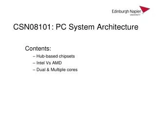
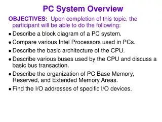
PC System Overview. OBJECTIVES: Upon completion of this topic, the participant will be able to do the following: Describe a block diagram of a PC system. Compare various Intel Processors used in PCs. Describe the basic architecture of the CPU.

E N D
PC System Overview OBJECTIVES: Upon completion of this topic, the participant will be able to do the following: • Describe a block diagram of a PC system. • Compare various Intel Processors used in PCs. • Describe the basic architecture of the CPU. • Describe various buses used by the CPU and discuss a basic bus transaction. • Describe the organization of PC Base Memory, Reserved, and Extended Memory Areas. • Find the I/O addresses of specific I/O devices.
NorthBridge(GMCH) Processor System memory FSB/Host Bus VGA PCIe x16 Bus DMI System management bus PCIe x1 SouthBridge(ICH) PCI Bus LAN FWH SIO Audio ClockGenerator USB LPC bus Host clock IDE PCI clock USB clock SATA Hublink clock KB Mouse Floppy Serial Parallel Chipset: North Bridge, South Bridge, & Firmware Hub Basic operational design is called its architecture • North Bridge • HOST-PCI Bridge • DRAM Controller • AGP Interface • South Bridge (ICH) • PCI-PCI Bridge • 8254 Timer; 8259 Intr. Ctlr; 8237 DMAC; RTC • EIDE Interface • USB Ctlr • Super I/O • Kybd/Mouse Ctlr • Floppy Ctlr • Serial & IR port • Parallel ports
Intel Processor Statistical Comparison Processor Tran- sistors Year External Bus Size Principle Features Internal Arch (register size) 86 1978 16 16 29K 16-bit architecture, basic segment protection 88 1979 16 8 29K Same as 86, but with 8-bit processor bus.(IBM PC) 286 1982 16 16 134K Introduced protected mode, access to 16 MB memory,. Intel 386TM 1985 32 32 275K 1st true 32-bit processor. Adds 32-bit reg extensions & paging,. Adds on-chip cache, floating-point unit. Intel 486TM 1989 32 64 1.2M Superscaler, Code & Data Cache, 1st 64 bit data bus Pentium® 1993 32 64 3.1M Integrated L2, Reg Renaming First P6 family processor 5.5M 1995 32 64 Pentium® Pro 7.5M 57 new instructions, Multiple Branch Prediction, Dataflow Analysis, Speculative Execution, 1997 Pentium® II 32 64 1999 Celeron® Pentium® III Pentium® 4 2000 32 64 42M Quad pumped Data bus yields > 400 M trans/sec
Intel Processor Statistical Comparison PC/AT Compatibility Standard # Integrated L2 * Protected Mode ** Quad pumped 100 808880286 80386 80486 Pentium® Pentium® Pentium®Pentium® Pro II 4 CPU 202432 32 32 36 36 36 Addr -BUS 1 MEG 16 MEG* 4 GIG * 4 GIG* 4 GIG* 64 GIG* 64 GIG*64 GIG* MEM SIZE VIRTUAL SIZE NA 1 GIG 64 TERA 64 TERA 64 TERA 64 TERA 64 TERA 64 TERA 8 16 32 32 64 64 64 64 D-BUS REG SIZE 16 16 32 32 32 32 32 32 # SEG. REGS 4 4 6 6 6 6 6 6 MATH 8087 80287 80387 On Chip On Chip On Chip On Chip On Chip BUS SPEED (MHz) 4.77, 8 8, 12 16, 25, 33 33, 50 50, 60, 66 60, 66 66,100 100/400** PAGING NO NO YES YES YES YES YES YES ON CHIP CACHE NO NO NO YES YES #YES #YES #YES “Virtual”address space simulates more memory than actually exists by using paging to allow the excess to be stored on hard disk and copied to RAM as required.
Instructions are Fetched from the code cache or external bus. 64-bits wide System Bus Front-End BTB(4K Entries) InstructionTLB/Prefetcher Instruction Decoder MicrocodeROM QuadPumped3.2 GB/sBus InterfaceUnit Trace Cache BTB(512 Entries) Trace Cache(12K μops) μop Queue Allocator / Register Renamer Memory μop Queue Integer / Floating Point μop Queue Memory Scheduler Fast Slow / General FP Scheduler Simple FP Application Register Set FP Register/Bypass L2 Cache(256K Byte 8-way)48 GB/s AGU AGU 2x ALU 2x ALU Slow ALU FP MMXSSE SSE2 FPMove LoadAddress StoreAddress SimpleInstr. SimpleInstr. ComplexInstr. 256 bits L1 Data Cache (8Kbyte 4-way) CPU Internal Architecture • The Heart of the PC is the Processor • Decoded by the decode unit so the CPU can execute them. • The ALUs Execute the instructions.
Power Address Bus A[35:3]# Ground RESET# BCLK CPU Data Bus D[63:0]# DBI[3:0]# ADS# REQ[4:0]# RS[2:0]# DSTB[3:0]# CPU Signals Required for operation • Multiple Power & Ground pins. • Processor Reset (input): • Clock (input): 66, 100, 133, 200 MHz depending on design. • The CPU uses this as the external bus clock. • Source Synchronous protocol uses strobes (i.e., DSTB[3:0]#) to latch data, implementing a 4X transfer rate. • “Quad pumping” example: A processor using a 100MHz external clock achieves an effective 400MHz transfer rate.
Address • Data • Control ADDRESS CPU MEMORY DATA ADS# REQ[4:0]# RS[2:0]# DSTB[3:0]# DBI[3:0]# I/O CONTROL Simplified Bus Introduction • Microprocessors use several buses to communicate with memory and I/O resources. • The Processor System Bus (PSB) or Host Bus or FSB (Front Side Bus) is the set of wires used to carry information to and from the processor. • In general, buses communicate three types of information:
Not Accessible D63:0 64 bit Memory CPU 0000FFFCH 0000FFFFH 64 KByte A[35:3], BE[7:0]# 00000000H 00000003H I/O Space CPU Bus Description • Address bus: The number of address lines determines the amount of memory supported. • The CPU address consists of two sets of signals: • The CPU uses A[35:3] to identify a group of 8 locations known as a Quadword (8 bytes). • Byte Enables address locations within a Quadword . • BE[7:0]# -- In effect a decode of the address lines A2-A0 which the CPU does not generate. • BE[7:0]# and other configuration signals appear on second packet of address phase.
CPU Bus Description • Data bus: A single transfer cycle can read or write up to 64 bits at a time (8 bytes). • D63:D0 (bi-directional): 64-bit data path to/from processor. • Note: This is a 32 bit CPU due to having 32 bits registers. • Control bus: Typical control bus signals are these: • ADS# (in/output):Address Strobe- CPU begins bus cycle. • REQ[4:0]# (input/output):Request- 5-bit code to identify the type of transaction, (memory or I/O, read or write). • RS[2:0]# (input):Response- 3 bit code to respond to CPU. • DSTB[3:0]# (output):Data Strobe- Used to latch data. • DBI[3:0]# (input/output):Data Block Inversion- Indicates current state of data bus (inverted or not).
Architectural State Architectural State Architectural State Architectural State ProcessorExecutionResources ProcessorExecutionResources ProcessorExecutionResources Hyper-Threading Technology Intel® NetBurst™ Microarchitecture Hyper-Threading Enabled Processor P6 Microarchitecture Dual Processor • HT Technology enables a single processor to execute 2 separate code streams (called threads) concurrently • HT technology allows 1 physical processor to appear as 2 “logical” processors to software (O/S and applications). • Each logical processor has its own architecture state with its own set of general-purpose and control registers • Some resources are shared (caches, exe units, buses, etc) HT technology can repeatedly switch from one set of data instructions to the other, every few nanoseconds. System Bus
A BUS CYCLE (transaction) begins when processor asserts ADS# while driving valid Address & Control signals. A BURST Cycle alwaystransfers 512 bits (8*64) [64 bytes] CPU only needs to output starting address to fill one cache line. BCLK0 ADS# Address & Byte Enables A[35:3]# Addr BE Transaction type/direction REQ[4:0}# RS[2:0}# Complete, Defer, Fail DRDY# Data Ready DATA[63:0]# Basic Bus Transaction Burst mode is used for all Cacheable cycles. Burst transfers occur in an address region that begins on a 64-byte boundary & the system board must calculate the 2nd, 3rd, etc burst addresses. 0-8 byte transfers for non-cacheable memory and I/O are also supported. Transaction ends when DRDY# is returned to the processor.
Source Synchronous Signalling • The Intel® Pentium® 4 processor supports the desktop system bus by delivering up to 6.4 Giga Bytes per second (GB/s) of data throughput. • This is accomplished through a physical signaling scheme which quad pumps data transfers over a 200-MHz clocked system bus • Source Synchronous Clocking sends a strobe signal in parallel with the data. (also used on Address Bus) • Data and STROBE are generated at the Driver
5 nanoseconds BCLK(200MHz)ADSTBAD[35:3]REQ[4:0] DSTBp#(@driver)DSTBn#(@driver) D#(@driver) Address BE / Config *SP1 SP2 * SP – Sub Phase Processor Source Synchronous Cycle Data/Address signals propagate toward their destinations at the same rate as accompanying strobes • Address Bus is Double Pumped. • SP1 – Address • SP2 – BE/Config • Data Bus is Quad-Pumped • Transfers 4 packets of data per BCLK cycle • 4 x 8bytes x 200M= 6.4 GB/sec.7
For compatibility, all processors start in real mode after reset. In order to maintain compatibility with the original PC's BIOS (and the DOS operating system), the PC memory map is limited to 1M byte in REAL MODE. ADDRESS FFFFFFFF FFFE0000 FFFE0000 10FFF0 10FFEF 100000 0FFFFF 0F0000 0EFFFF 0E0000 0DFFFF 0C0000 OBFFFF 0A0000 09FFFF 000000 DESCRIPTION 128K ROM OR DRAM EXTENDED SYSTEM MEMORY HIGH MEMORY AREA 64K ROM OR DRAM 64K ROM OR DRAM 128K I/O EXPANSION ROM 128K VIDEO RAM 640K SYSTEM MEMORY FUNCTION RESERVED FOR SYSTEM ON BOARD DRAM ON BOARD DRAM ROM BIOS OR RAM BIOS EXTENSION OR RAM RESERVED FOR ROM ON I/O ADAPTERS DISPLAY BUFFER REAL MODE ON BOARD DRAM 1M byte System Memory Map • The original PC used an 8088 microprocessor limited the memory map to a size of 1M Byte.
A0000h 640K 512K 256K Operation System and Application Programs 128K 64K 0500h BIOS DATA 0400h Interrupt Vector Table 0000h Base (Conventional) Memory • 1st 640 KB of system memory is “conventional” memory. • Sometimes referred to as DOS memory--refers to the memory-addressing scheme used in the original IBM and compatible PCs. • The 1st 640 KB is used by: • System BIOS • Interrupt Vector Table: 0-300h • BIOS data area: 400h-500h • Operating System and application programs
Reserved Memory • Memory from 640K-1MB is for system use and is typically not available for applications. • Display adapter memory is typically on the display adapter itself. • Video BIOS may be on the display adapter. • 0E0000H to 0FFFFFH is reserved for BIOS. • Upper 64K (F0000-FFFFF) for POST/ Runtime BIOS FFFFFh F0000h EFFFFh E0000h D0000h C8000h C7FFFh C0000h B8000h B0000h A0000h POST Runtime BIOS Reserved for System BIOS OPTIONAL ADAPTER CARD ROMS` VIDEO BIOS (ROM) CGA Video Memory on VIDEO ADAPTERS (NOT System DRAM) MDA VGA Sometimes this area is referred to as Upper Memory Blocks (UMB)
Extended Memory • Memory above 1MB is called Extended Memory. • PCs may come with 128M bytes or more installed. • Added as an extension to the base 1 MB--the limit of memory addressability of the original PC processor (8088). • Beginning with the PC/AT, it became possible to address >1MB of memory by putting the CPU in protected mode. • Protected mode is used to access extended memory which is used with Windows, Unix, Linux, etc. • With DOS, extended memory is typically not available at all. • With the exception of the 1st 65,520 bytes (High Memory Area), extended memory is not accessible in real mode. • HMA is accessible in Real Mode (usually used for DOS)using a driver which contains A20 Handler Software.
I/O Address Map • Intel IA-32 processors implement a separate I/O (input/output) space apart from memory address space. • An I/O PORT is an address in I/O space in which you can read or write information (e.g., port 3F8 is a serial port ) • Clearly separates Memory & I/O devices by using IN/OUT instructions for I/O, and MOV instructions for Memory transfers • The size of the Intel I/O space is 64K addresses. • Since the 16-bit DX register holds the address for I/O space accesses, FFFF (64K) is the max possible address. • Most of the I/O assignments are industry standard. • Many devices have several ports assigned to them. • Some Ports such as 78/79, 90/92, 2E/2F hex are Vendor specific and are used to implement board specific features.
Address(in hex) Size Description 0000 - 000F 0020 - 0021 002E 002F 0040 - 0043 0060 0061 0064 0070, bit 7 0070, bits 6:0 0071 0078 0079 0080 - 008F 00A0 - 00A1 00B2 - 00B3 00C0 - 00DE 00F0 0170 - 0177 16 bytes 2 bytes 1 byte 1 byte 4 bytes 1 byte 1 byte 1 byte 1 bit 7 bits 1 byte 1 byte 1 byte 16 bytes 2 bytes 2 bytes 31 bytes 1 byte 8 bytes DMA 1 Interrupt Controller 1 SIO Index Register SIO Data Register Timer 1 Keyboard Controller Data Byte NMI, speaker control Kbd Controller, CMD/STAT Byte Enable NMI Real Time Clock, Address Real Time Clock, Data Reserved Brd. Config. Reserved Brd. Config. DMA Page Register Interrupt Controller 2 APM control port DMA 2 Reset Numeric Error Secondary IDE Channel Example I/O Address Map
Example I/O Address Map (Cont.) Address (hex) Size Description 01F0 - 01F7 0278 - 027B 02F8 - 02FF 0376 0377 0378 - 037F 03BC - 03BF 03E8 - 03EF 03F0 - 03F5 03F6 03F7 (write) 03F7, bit 7 03F7, bits 6:0 03F8 - 03FF OCF8 - 0CFB 0CF9 0CFC - OCFF FF00 - FF07 8 bytes 4 bytes 8 bytes 1 byte 1 byte 8 bytes 4 bytes 8 bytes 6 bytes 1 byte 1 byte 1 bit 7 bits 8 bytes 4 bytes 1 byte 4 bytes 8 bytes Primary IDE Channel Parallel Port 2 On - Board Serial Port 2 Sec IDE Chan Cmd Port Sec IDE Chan Stat Port Parallel Port 1 Parallel Port x Serial Port 3 Floppy Channel 1 Pri IDE Chan Cmd Port Floppy Chan 1 Cmd Floppy Disk Chg Chan 1 Pri IDE Chan Status Port On - Board Serial Port 1 PCI Config Address Reg Reset Control Register PCI Config Data Reg IDE Bus Master Reg.
NorthBridge(GMCH) Processor System memory FSB/Host Bus VGA PCIe x16 Bus DMI System management bus PCIe x1 SouthBridge(ICH) PCI Bus LAN FWH SIO Audio ClockGenerator USB LPC bus Host clock IDE PCI clock USB clock SATA Hublink clock KB Mouse Floppy Serial Parallel Review & Summary • PC Block diagram. • PC/AT (80286) set a compatibility standard. • The basic operational design is called its architecture. • The Chipset consists of the North Bridge, South Bridge and Firmware Hub • North Bridge: HOST-PCI Bridge / DRAM Controller. • South Bridge (ICH): PCI-PCI Bridge; 8254 Timer; 8259 Intr. Ctlr 8237 DMAC; RTC; EIDE I/F; USB Ctlr • Super I/O: Kybd/Mse; Floppy; Serial/IR & Parallel
Review & Summary • Basic architecture of a desktop system. • The heart of a PC is the Microprocessor. • Instructions are Fetched from the cache or the external bus; the decode unit Decodes instructions; ALUs Execute the instructions. • Microprocessors use Address, Data, & Control buses to communicate with memory and I/O resources. • A BUS CYCLE begins when the Processor asserts ADS# while driving valid Address and Control signals. • Address Bus A[35:3] (includes Byte Enables BE[7:0]#) • Data Bus D[63:0]: 64-bit data path to or from the processor. • Control bus signals: ADS#; REQ#; RS#; DSTB#; & DBI#
Review & Summary • The organization of PC Memory. • The 1st 640 KB is called Conventional or Base Memory. • Reserved Memory--memory from 640K to 1M byte is for system use and is not typically available for applications. • Extended Memory: Memory above 1MB; CPU uses Protected Mode to access memory above 1 Mega Byte. • The the organization of the PC’s I/O Address Map. • The size of the Intel I/O space is 64K addresses. • Intel microprocessors have a separate I/O address map. • Most of the I/O assignments are industry standard.