Download

1 / 22
220 likes | 429 Views
Keystone Family PCIE. Eric Ding. Agenda. PCIE Overview Address Translation Configuration PCIE boot demo. Agenda. PCIE Overview Address Translation Configuration PCIE boot demo. PCIE Topology Example. PCIE: a tree structure with nodes connected to each other via point-to-point links.

E N D
Keystone Family PCIE Eric Ding
Agenda • PCIE Overview • Address Translation • Configuration • PCIE boot demo
Agenda • PCIE Overview • Address Translation • Configuration • PCIE boot demo
PCIE Topology Example • PCIE: a tree structure with nodes connected to each other via point-to-point links. • The root node is called the root complex (RC). • The leaf nodes are called end points (EP) and the nodes that connect multiple devices to each other are called switches (SW).
Shannon Functional Diagram TCI6678 (Shannon) System Elements . . . 8 C66x Cores Power Mgt SysMon Debug EDMA C66x core Peripherals and I/O L2 Memory sRIO TSIP Navigator L1 D L1 P Flash PCIe UART SPI, I2C TeraNet HyperLink Memory System Enet Switch Crypto/IPSec CoProcessor Multicore MemoryController Multicore DDR-3 64b Shared Memory Packet CoProcessor SGMII SGMII 5
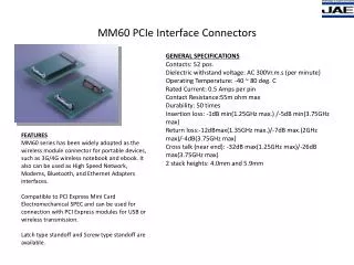
PCIE Features • PCI-SIG: PCI Express Base Specification (Rev. 2.0) • Root Complex (RC) and End Point (EP) operation modes. • In EP mode, supports both legacy EP mode and native PCIE EP mode. • Set from bootstrap pins PCIESSMODE[1:0] at power-up (00->EP, 01->Legacy EP, 10->RC). • Software overwrites the setting by changing the PCIESSMODE bits in the DEVSTAT register. • Gen1 (2.5 Gbps) and Gen2 (5.0 Gbps) • x2 lanes • Outbound/Inbound max payload size of 128/256 bytes
Agenda • PCIE Overview • Address Translation • Configuration • PCIE boot demo
Address Translation • PCIE device uses PCIE address to Tx/Rx packets over a PCIE link • Outbound transfer means the local device initiates the transactions to write to or read from the external device. The CPU or the device-level EDMA is used for outbound data transfer. The PCIE module does not have built-in EDMA. • Inbound transfer means the external device initiates the transactions to write to or read from the local device. The PCIE module has a master port to transfer the data to or from the device memory; no CPU or EDMA is needed for inbound transfer in the local device. • BAR: used to accept/reject TLP.
Outbound Translation - 1 • PCIE data space 256 MB (0x6000_0000~0x6FFF_FFFF) • Enable/disable through CMD_STATUS register • When enabled, the outbound PCIE address (0x6000_0000~0x6FFF_FFFF) can be modified to a new address based on the outbound translation rules • Equally divided into 32 regions • Registers for OB • OB_SIZE: identify the size of 32 equally-sized translation regions to be 1MB/2MB/4MB/8MB • OB_OFFSET_INDEXn: represent bits[31:20] of the PCIE address for 32-bit or 64-bit addressing; not all bits will be used (depend on OB_SIZE); bit[0] enables the outbound region • OB_OFFSETn_HI: represent bits[63:32] of the PCIe address for 64-bit addressing; must be zero for 32-bit addressing
Outbound Translation - 2 • Example: • OB_SIZE: 1 MB; OB_OFFSET_INDEX0 = 0x9000_0001; OB_OFFSET0_HI = 0x0; PCIE data space address: 0x6001_5678; What is the translated PCIE address? • Calculation: • OB_SIZE = 1 MB == using bit [24:20] for region indexing • Bits [24:20] of 0x6001_5678 = 00000b = 0 == so Region 0 • Using OB_OFFSET_INDEX0 and OB_OFFSET0_HI • Then the translated PCIE address = bits[31:20] of 0x9000_0000 + bits[19:0] of 0x6001_5678 = 0x9001_5678
Inbound Translation - 1 • Enable/disable through CMD_STATUS register • Registers for IB • BARn: two BARs (BAR0~1) in RC mode and six BARs (BAR0~5) in EP mode; overlay with BAR mask • Four IB regions • IB_BARn: which BAR for inbound transaction • IB_STARTn_LO: the starting address bits [31:0] in PCIE address • IB_STARTn_HI: the starting address bits [63:32] in PCIE address • IB_OFFSETn: the internal bus address that will be the starting point of the mapped or translated PCIE address region • BAR0 cannot be remapped to any other location than to PCIE application registers (starting from 0x2180_0000 in KeyStone device). It allows the RC device to control EP in the absence of dedicated software running on EP.
Inbound Translation - 2 • Example: • For a 32-bit BAR, BAR1 = 0xF740_0000; IB_BAR0 = 1; IB_START0_LO = 0xF740_0000; IB_START0_HI = 0x0; IB_OFFSET0 = 0x1080_0000 • For PCIE address 0xF740_1234, what is the DSP device’s internal address? • Calculation: • The incoming address of 0xF740_1234 matches the range (determined by BAR mask) of BAR1, it is accepted • IB_BAR0 = 1 == the first IB region is used • DSP internal address: 0xF740_1234 – 0xF740_0000 + 0x1080_0000 = 0x1080_1234 (local L2)
Agenda • PCIE Overview • Address Translation • Configuration • PCIE boot demo
PCIE Initialization • Boot mode: PCIE boot by selecting pins on 6678/6670 EVM boards • IBL code • PLL workaround (6678 Errata, advisory 8) • Power-up PCIE • Configure PLL • Configure PCIE registers • Waiting for PCIE link-up • Stay inside IBL, monitor the magic address (6678: 0x87FFFC; 6670: 0x8FFFFC) for secondary boot
Agenda • PCIE Overview • Address Translation • Configuration • PCIE boot demo
Demo Setup • An AMC to PCIE adaptor card • A TMS320C66xxL EVM card • A Linux PC (Tested on Ubuntu 10.04, 32/64-bit) • A UART cable
PCIE Enumeration • PCIE Enumeration • From Linux • local-ubuntu:~$ lspci –n • …. • 00:1f.3 0c05: 8086:27da (rev 01) • 01:00.0 0480: 104c:b005 (rev 01) • 03:00.0 0200: 14e4:1677 (rev 01) Or • local-ubuntu:~$ lspci • …. • 00:1f.3 SMBus: Intel Corporation N10/ICH 7 Family SMBus Controller (rev 01) • 01:00.0 Multimedia controller: Texas Instruments Device b005 (rev 01) • From DSP (JTAG if available)
PCIE Linux Host Loader Code • Mapping between PC memory and DSP memory • Configure the PCIE inbound/outbound address translation • Provide DSP memory read/write API: • Uint32 ReadDSPMemory(Uint32 coreNum, Uint32 DSPMemAddr, Uint32 *buffer, Uint32 length) • Uint32 WriteDSPMemory(Uint32 coreNum, Uint32 DSPMemAddr, Uint32 *buffer, Uint32 length) • Parse the boot example header array to load data into DSP • Write the boot entry address into the magic address on core 0 to jump start • Need to be compiled and inserted as kernel module
PCIE Boot Examples • “Hello world” and POST examples under MCSDK (http://software-dl.ti.com/sdoemb/sdoemb_public_sw/bios_mcsdk/latest/index_FDS.html) • Convert the ELF out file into header file (data array) to be loaded by Linux host into DSP • View the results via UART (minicom on Linux)
Demo - Linux • View results from “dmesg” • Hello World: • [ 159.915074] Finding the device.... • [ 159.915087] Found TI device • [ 159.915089] TI device: vendor=0x104c, dev=0xb005, irq=0x0000000b • [ 159.915090] Reading the BAR areas.... • [ 159.915633] Enabling the device.... • [ 159.915688] pci 0000:04:00.0: PCI INT A -> GSI 16 (level, low) -> IRQ 16 • [ 159.915693] pci 0000:04:00.0: setting latency timer to 64 • [ 159.915702] Access PCIE application register .... • [ 159.915706] Registering the irq 11 ... • [ 159.915718] Boot entry address is 0x1082cc00 • [ 159.918251] Total 4 sections, 0xd748 bytes of data written to core 0 • [ 159.976877] Boot entry address is 0x8000cd60 • [ 159.979045] Total 4 sections, 0xda04 bytes of data written to core 9 • POST: • [ 96.779446] Finding the device.... • [ 96.779463] Found TI device • [ 96.779464] TI device: vendor=0x104c, dev=0xb005, irq=0x0000000b • [ 96.779465] Reading the BAR areas.... • [ 96.780067] Enabling the device.... • [ 96.780080] pci 0000:04:00.0: PCI INT A -> GSI 16 (level, low) -> IRQ 16 • [ 96.780085] pci 0000:04:00.0: setting latency timer to 64 • [ 96.780094] Access PCIE application register .... • [ 96.780098] Registering the irq 11 ... • [ 96.780109] Boot entry address is 0x 83a560 • [ 96.782119] Total 3 sections, 0xb190 bytes of data written to core 0