Download
1 / 12
120 likes | 222 Views
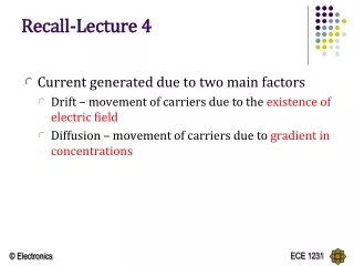
RECALL LECTURE 9. Introduction to BJT 3 modes of operation Cut-off Active Saturation Active mode operation of NPN. NPN. PNP. I E = I S [ e VBE / VT ]. I E = I S [ e VEB / VT ]. I C = I B. I C = I E. I E = I B ( + 1). = [ / 1 - ]. = [ / + 1 ].

E N D
RECALL LECTURE 9 • Introduction to BJT • 3 modes of operation • Cut-off • Active • Saturation • Active mode operation of NPN
NPN PNP IE = IS [ e VBE / VT ] IE = IS [ e VEB/ VT] IC = IB IC = IE IE = IB(+ 1) = [/ 1 - ] = [ / + 1 ] Based on KCL: IE = IC + IB
DC analysis of BJT • BE Loop (EB Loop) – VBE for npn and VEB for pnp • CE Loop (EC Loop) - VCE for npn and VEC for pnp • When node voltages are known, branch current equations can be used.
Common-Emitter Circuit • The figures below is showing a common-emitter circuit with an npn transistor and the dc equivalent circuit. • Assume that the B-E junction is forward biased, so the voltage drop across that junction is the cut-in or turn-on voltage VBE (on). Unless given , always assume VBE = 0.7V
Common-Emitter Circuit • The base current: KVL at B-E loop • Implicitly assuming that VBB > VBE (on), which means that IB > 0. When VBB < VBE (on), the transistor is cut off and IB = 0.
Common-Emitter Circuit • In the C-E loop of the circuit, we can use: and • Implicitly assuming that the transistor is biased in the forward-active mode.
Examples BJT DC Analysis
Common-Emitter Circuit Example Calculate the base, collector and emitter currents and the C-E voltage for a common-emitter circuit by considering VBB = 4 V, RB = 220kΩ, RC = 2 kΩ, VCC = 10 V, VBE (on) = 0.7 V andβ = 200.
BJT Circuits at DC = 0.99 KVL at BE loop: 0.7 + IERE – 4 = 0 IE = 3.3 / 3.3 = 1 mA Hence, IC = IE= 0.99 mA IB = IE – IC = 0.01 mA KVL at CE loop: ICRC + VCE + IERE – 10 = 0 VCE = 10 – 3.3 – 4.653 = 2.047 V
Common-Emitter Circuit - PNP Example Find IB, IC, IE and RC such that VEC = ½ VCC for a common-emitter circuit. Consider: VBB = 1.5 V, RB = 580 Ω, VCC = 5 V, VEB (on) = 0.6 V, β = 100.
IE EXAMPLE Given = 75 and VEC = 6V. Find the values of the labelled parameters, RC and IE,