Download
1 / 40
620 likes | 1.03k Views
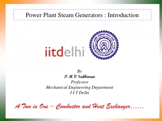
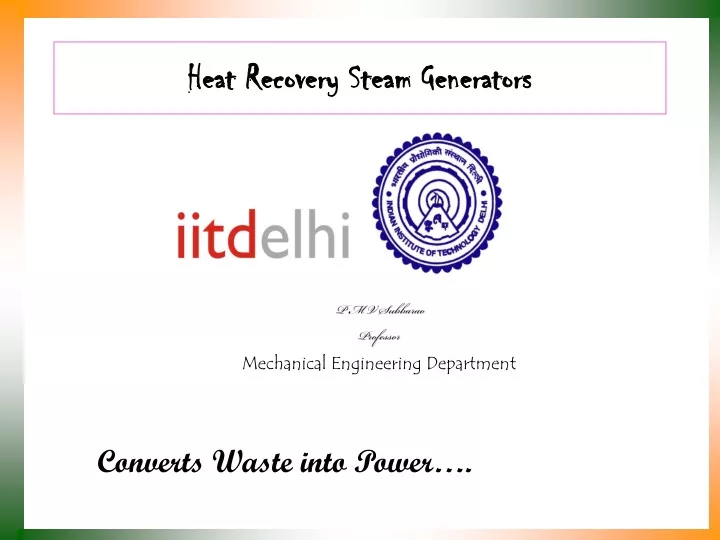
Heat Recovery Steam Generators. P M V Subbarao Professor Mechanical Engineering Department. Converts Waste into Power…. COMBINED CYCLE POWER PLANT. GAS INLET. P=10bar. CC. T=150 0 C. T=850 0 C. P=10bar. TURBINE. G. COMP. T=100 0 C. T=50 0 C. STACK. P=2bar. P=1bar. T=550 0 C.

E N D
Heat Recovery Steam Generators P M V Subbarao Professor Mechanical Engineering Department Converts Waste into Power….
COMBINED CYCLE POWER PLANT GAS INLET P=10bar CC T=1500C T=8500C P=10bar TURBINE G COMP T=1000C T=500C STACK P=2bar P=1bar T=5500C HP IP LP AIR INLET HRSG T=5000C P=170bar TURBINE T=500C G PUMP P=1bar P=.1 bar T=500C T=600C CONDENSER
Types of HRSG • Basic types of standard design of heat recovery steam generators are differentiated by the direction of the flue gases flow. • Vertical HRSG • Small footprint • Simple concept of service • Hanging design of heating surfaces • Horizontal HRSG • Small construction height • High cycling ability • Operational flexibility • Hanging design of heating surfaces
Horizontal HRSG Vertical HRSG
~5500C ~1000C ~400C
~1000C ~5500C Schematic Diagram of a Simple HRSG
Super heater configurations • Three basic super heater designs are: • Horizontal Tube, • Vertical Tube, and • I-Frame
S1 S2 Convective Super heater (Horizontal)
S1 S2 Convective Superheater (Pendant)
Types of Evaporator Sections • D-Frame evaporator layout • O-Frame evaporator layout • A-Frame evaporator layout • I-Frame evaporator layout • Horizontal tube evaporator layout
This configuration is very popular for HRSG units recovering heat from small gas turbines and diesel engines. • It is a very compact design and can be shipped totally assembled. • It is limited, however, since the bent tube arrangement quickly causes the module to exceed shipping limitations for units having a large gas flow
O-Frame evaporator layout.This configuration has probably been used for more years than any of the others. It has the advantage of the upper header being configured as the steam separation drum. Or, the upper header can be connected to the steam drum by risers, allowing more than one O-Frame evaporator to be connected to the same steam drum, resulting in shipable modules being able to handle very large gas flows.
A-Frame evaporator layout. This configuration is simply a variation of the O-Frame Evaporator. It was popular for services with a large amount of ash, since the center area between the lower drums could be configured as a hopper to collect and remove solid particles.
I-Frame evaporator layout. In the past twenty years, this configuration has become the most popular. This type module can be built in multiple axial modules or in multiple lateral modules, allowing it to be designed to accept any gas flow. There are numerous variations of this design where tube bundles may contain one, two, or three rows of tubes per header. It is also, normally, more economical to manufacture, ship and field construct. The tube bundles may be shipped to field installed in the modules, or as loose bundles which are installed into a field erected shell.
It has similar size limitations due to shipping restrictions similar to the O-frame modules. It is generally a less expensive unit to manufacture than the other configurations.
Today’s Limits • Limits are, in this case, meant to be state of the art values of key performance factors of a HRSG application • limits driven by economical and technical considerations. • Triple Pressure Reheat Drum Type Boilers, natural circulation: