Download
1 / 42
420 likes | 456 Views
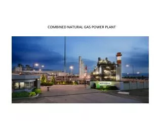
Power Plant Steam Generators : Introduction. By P M V Subbarao Professor Mechanical Engineering Department I I T Delhi. A Two in One – Combustor and Heat Exchanger……. The Steam Power Plant. Executes a Thermodynamic Cycle using an assembly of CVs.

E N D
Power Plant Steam Generators : Introduction By P M V Subbarao Professor Mechanical Engineering Department I I T Delhi A Two in One – Combustor and Heat Exchanger……
The Steam Power Plant Executes a Thermodynamic Cycle using an assembly of CVs
Cause – Effect Analysis of A Steam Generator • Combustion is a primary cause. • Steam Generation is an ultimate effect. • Heat transfer is a mediation. • Combustion caused the generation of heat in side furnace volume. • Heat generation caused the production of high temperature gases. • These high temperature gases caused the Radiation and convection heat transfer processes. • Heat Transfer processes carried the thermal energy to furnace wall & steam tubes. • Conduction through the tubes and walls caused the convection inside the tubes. • Convection Caused the generation of steam. • Few hundred years of ingenious trials lead to a Scientific technologty.
Water Tube Boilers: The Steam Generators • As industry developed during 19th century, so the use of boilers for raising steam became widespread. • Disastrous explosions sometimes occurred. • Boilers of that period consisted of heated pressure vessels of large diameter. • These are subject to internal pressure which is tensile stresses in the walls of the enclosure. • The value of stress, known as ‘hoop stress’ is given by
Steam generator versus steam boiler • Opposite the principle of the steam boilers, the water in the steam generators evaporates inside the tube winded up into serial connected tube coils. • The feed water is heated up to the evaporation temperature and then evaporated. • The intensity of the heat, the feed water flow and the size/length of the tube are adapted, so that the water is exactly fully evaporated at the exit of the tube. • This ensures a very small water and steam volume (content of the pressure vessel). • Thus there are no buffer in a steam generator, and is it temporary overloaded.
Steam generator versus steam boiler • The advantages using a steam generator compare to conventional steam boilers: • Easy to operate - normally no requirement for boiler authorization. • Rapid start-up and establishing full steam pressure Compact and easy to adapt in the existing machinery arrangement • Price attractive - especially at low steam rates.
DPNL SH R H T R drum screen tubes Platen SHTR LTSH Economiser stack BCW pump Furnace APH ESP ID Fan Bottom ash Thermal Structure of A Subcritical SG
S1 S2 Convective Superheater (Pendant)
S1 S2 Convective Superheater (Horizontal)
The Steam Generator : The water tube boiler • As you can see, the Water Tube Boiler (below) looks very complicated. • Thousands of tubes are placed in strategic location to optimize the exchange of energy from the heat to the water in the tubes. • These types of boilers are most common because of their ability to deliver large quantities of steam. • The large tube like structure at the top of the boiler is called the steam drum. • The hundreds of tube start and eventually end up at the steam drum.
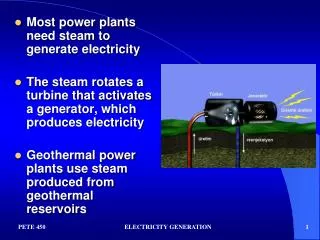
Steam Generator Theory • Within the boiler, fuel and air are force into the furnace by the burner. • There, it burns to produce heat. • From there, the heat (flue gases) travel throughout the boiler. • The water absorbs the heat, and eventually absorb enough to change into a gaseous state - steam. • To the left is the basic theoretical design of a modern boiler. • Boiler makers have developed various designs to squeeze the most energy out of fuel and to maximized its transfer to the water.
Steam Generator Theory • Water enters the boiler, preheated, at the top. • The hot water naturally circulates through the tubes down to the lower area where it is hot. • The water heats up and flows back to the steam drum where the steam collects. • Not all the water gets turn to steam, so the process starts again. • Water keeps on circulating until it becomes steam. • Meanwhile, the control system is taking the temperature of the steam drum, along with numerous other readings, to determine if it should keep the burner burning, or shut it down.
Steam Generator Theory : Water Side • As well, sensors control the amount of water entering the boiler, this water is know as feedwater. • Feedwater is not your regular drinking water. • It is treated with chemicals to neutralize various minerals in the water, which untreated, would cling to the tubes clogging or worst, rusting them. • This would make the boiler expensive to operate because it would not be very efficient.
Steam Generator Theory : Fire Side • On the fire side of the boiler, carbon deposit resulting from improper combustion or impurities in the fuel can accumulate on the outer surface of the water tube. • This creates an insulation which quickly decrease the energy transfer from the heat to the water. • To remedy this problem the engineer will carry out soot blowing. At a specified time the engineer uses a long tool and insert it into the fire side of the boiler.. • This device, which looks like a lance, has a tip at the end which "blows" steam. • This blowing action of the steam "scrubs" the outside of the water tubes, cleaning the carbon build up.
Scaling of Steam Generators • This blowing action of the steam "scrubs" the outside of the water tubes, cleaning the carbon build up. • Water tube boilers can have pressures from 7 bar to as high as 350 bar. • The steam temperature's can vary between saturated steam, 100 degrees Celsius steam with particle of water, or be as high as 600 - 650 degrees Celsius, know as superheated steam or dry steam • The performance of boiler is generally referred to as tons of steam produced in one hour. • In water tube boilers that could be as low as 1.5 t/hr to as high as 2500 t/hr.
Role of SG in Rankine Cycle Perform Using Natural resources of energy …….
Economics of Flow Steam generation Supercritical Steam Generation Subcritical Flow Boiling Pump Exit
Natural Circulation Boiler Dry Steam to Super heaters Pump Exit Wet Steam Hot Water
Forced Circulation Boiler Dry Steam to Super heaters Pump Exit Wet Steam Hot Water Recirculation Pump
Once Through Boiler Dry Steam to Super heaters Hot Water Pump
Once Through Subcritical Steam Generator Once-through tangential fired Max. continuous rating: 520 kg/sMax.Steam temperature outlet: 540°CLive steam pressure outlet: > 18.3 MPa
Major Components of Coal Fired Steam Generator Crushed to small pieces of about 20 mm diameter ~600mm Offline Online
Design Steps for Steam Generators • Thermodynamic Design • Air/fuel ratio • Specific Size/Output. • Efficiency • Thermodynamic Parameters. • Heats Transfer based Design • Surface area of various parts. • Materials used for various parts. • Geometry of various parts. • Detailed Temperature distribution. • Constructional details.
Design Steps for Steam Generators • Hydraulic Design. • Pressure distribution/drop in various parts • Velocity distribution. • Hydraulic parameters. • Design Optimization. • Mechanical Design.
Steam Generator Specifications • Steam • Flow rate , Pressure & Temperature • Feed Water • Economizer inlet temperature • Fuel • Type, Ultimate Analysis, Heating value & Physical Properties • Sorbent • Emissions • SO2 , Nox & Particulate
Steam Generator Specifications • Pressure Drop • Solid Waste • Ash Deposit system • Auxiliaries • Site • Personnel • Evaluation Criteria • Special Parameters • Heat Recovery SG • Flue gas amount composition • Gas temperature at inlet • Back pressure of Turbine Pinch point.
Steam Generator Design Methodology • Preliminary Design • Useful for estimation of budget price • Detailed proposal Design • Essential for making a detailed competitive bid. • Final Design • Used in preparation of manufacturing drawings
Preliminary Design • Primitive First Law Analysis of various controls volumes. • INPUT: Steam conditions and Fuel Analysis • Database: Design data of previous plants. • Procedure: Interpolation or Extrapolation of past data. • Overall size • Weight • Cost of the plant • Commercial Software Packages available – CFBCAD for Fluidized Bed Boilers.
Detailed Proposal Design • Detailed study and Review of parameters of SG w.r.t. • Steam • Fuel • Environment • Thermodynamic Design • Heats Transfer based Design • Hydraulic Design. • Design Optimization. • Mechanical Design.
Combustion Safeguards and Controls • Furnace Explosion : The ignition and almost instantaneous combustion of highly inflammable gas or vapour or dust accumulated in furnace. • Conditions leading to Furnace Explosion: • Accumulation of unburned fuel. • Air and fuel in an explosive mixture. • Source of ignition. -- hot furnace walls, improper ignition timing, faulty torch etc. • Types of Furnace Explosions: • Gas explosions and coal dust explosions. • Primary and Secondary. • Reasons for increased number of furnace explosions: • Large Boilers -- higher burner capacity • Compact furnaces. • Low fire box temperatures in water tube boilers. • New fuels.
Causes of Fire Explosions • Flame failure due to liquids or inert gases entering the boiler fuel system. • Insufficient purge before lighting the first burner. • Human error. • Faulty automatic fuel regulating controls. • Fuel shutoff valve leakage. • Unbalanced fuel/air ratio. • Faulty fuel supply systems. • Loss of furnace draft. • Faulty pilot igniters.
Furnace Controls • Manual Control • Remote Manual Sequence Control • Automatic Sequence Control System. • Degree of Automation: • Manual • Supervised manual • Automatic nonrecycling • Automatic recycling.
Burner Flame Safeguard System • An arrangement of flame detector, interlocks and relays • to sense the presence of a proper flame • cause fuel to be shut of to the furnace during hazardous conditions. • Prevent Boiler and Furnace explosions.