Download
1 / 19
230 likes | 952 Views
Heat Pipe Heat Recovery System. Ashley Archibald Thomas Dean Christopher Johnson Tyler Norbut Daniela Wagus. Introduction to PoolPak . PoolPak International is a leader in the manufacture of indoor pool dehumidification equipment.

E N D
Heat Pipe Heat Recovery System Ashley Archibald Thomas Dean Christopher Johnson Tyler Norbut Daniela Wagus
Introduction to PoolPak PoolPak International is a leader in the manufacture of indoor pool dehumidification equipment. NEED: Heat Pipe for Next Generation Dehumidification Equipment to pre-heat incoming air
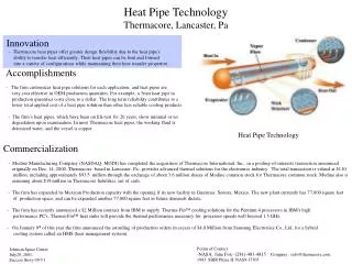
6 6 1 2 3 4 5 Splitter Plate Pool How a Heat Pipe Works • Heat Enters (warm indoor air) • Refrigerant Evaporates • Vapor Flow upwards • Cool Air Enters • Vapor Condenses, cool air is pre-heated • Liquid Return via gravity Heat Pipe
Project Description • Develop a mathematical design tool • will predict heat pipe behavior (for validation) • will compute heat pipe size (as design tool) • Build a heat pipe prototypes • Develop test set-ups for prototype • Evaluate test results against predicted results to validate our model
Mathematical ModelPrototype Design Tool • Wants: • Accurate in predicting the behavior of heat pipe • Calculated vs. measured value: ± 5% • User-friendly • symbolic mathematics • Explanations/instructions • Organized inputs according to supplier information • Easily varied inputs • Feasibility • Low Cost ~ $0 • Available or free software • Visible step-by-step procedure • Fast calculations: < 5 min • Constraints: • Vertical, finned, continuous tube heat pipe • Model parameters to facilitate validation through tests
Concept Selection Selected to create our Mathematical Design Tool with MathCAD, employing level one complexity and assumptions
Mathematical Model • System of equations to predict the performance of a heat pipe • Focus on internal behavior but external parameters will be used to determine internal properties • Based upon assumptions to avoid internal limitations • Designed to enable validation with measurable data from Tests
Mathematical Model Design • Assumptions • Mass flow rates of condensed and evaporated refrigerant are equal • Resistance due to fouling is negligible • Temperature of Vapor = Temperature of Condensate • Temperature of Evaporator Wall = Temperature of Warm Airflow • Temperature gradient through pipe, energy loss due to dissimilar shear forces of two-phase flow is neglected graduate level research When we created our mathematical model, our outputs were chosen based upon the easiest validation of our equations. To use the model as a design tool, equations can be manipulated to produce the desired outputs.
Validation Inputs Refrigerant and pipe properties Incoming air properties Air flow rates Length of evaporator & condenser Validation Outputs Heat transferred Mass flow rate of refrigerant Temperatures of outgoing air Optimal volume of refrigerant Design Inputs Refrigerant and pipe properties Incoming air properties Air flow rates Desired output temperature Design Outputs Heat transferred Mass flow rate of refrigerant Optimal length of evaporator & condenser Optimal volume of refrigerant Mathematical Model Design
Validation of Concept Step 1. Creation of Prototype Heat Pipes Step 2. Experimental prototype testing Step 3. Comparison between experimental values and mathematical model outputs In order to validate the internal behavior predicted by our mathematical model, we must evaluate the external properties of the heat pipe and find a relationship between the external and internal parameters.
Heat Pipe Prototypes • 36 tubes, one row of coils • Aluminum finned • Header Pipe • 1st Prototype total length = 52.2 in • 2nd Prototype total length = 40.5 • Refrigerant R22 used
Prototype Testing • Tests for Validation • Overall Heat pipe length • Multiple refrigerants • Variable airflow rates • Variable air temperatures • Volume of refrigerant
Validation Large Heat Pipe, Run #2 0.12531 kg/s in evaporator section 0.12500 kg/s in condenser section Recall: Assumption: Mass flows equal Validation: Difference 0.25%
Cost Analysis Other expenditures include the time Team 3, PoolPak and UD professors invested into the project. There were also costs associated with the energy and resources used during testing of the prototype.
Transition Plan Restructure Validation Model into Design Tool Path Forward Recommendations: • Math Modeling Tool • Remove assumptions • Testing • Vary lengths of heat pipe sections • Test a smaller header and place in warm duct • Validation • Numerical Validation with commercial program
Acknowledgements Ken Cooper Pat Reynolds Tim Sechrist Lan Xie George Emenheiser Steve Fisher Tim Thompson Dr. Keefe Dr. Advani Dr. Wang