Download
1 / 43
430 likes | 555 Views
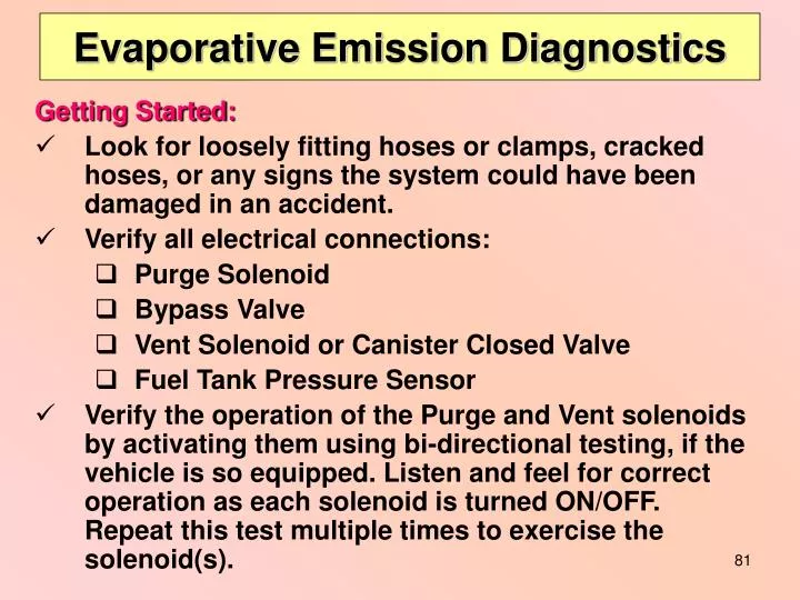
Evaporative Emission Diagnostics. Getting Started: Look for loosely fitting hoses or clamps, cracked hoses, or any signs the system could have been damaged in an accident. Verify all electrical connections: Purge Solenoid Bypass Valve Vent Solenoid or Canister Closed Valve

E N D
Evaporative Emission Diagnostics Getting Started: • Look for loosely fitting hoses or clamps, cracked hoses, or any signs the system could have been damaged in an accident. • Verify all electrical connections: • Purge Solenoid • Bypass Valve • Vent Solenoid or Canister Closed Valve • Fuel Tank Pressure Sensor • Verify the operation of the Purge and Vent solenoids by activating them using bi-directional testing, if the vehicle is so equipped. Listen and feel for correct operation as each solenoid is turned ON/OFF. Repeat this test multiple times to exercise the solenoid(s).
EVAP Leak Detection Equipment A typical EVAP Leak Detection station should consist of: • An appropriate EVAP Leak Detection/Smoke machine • Nitrogen bottle and regulator • Cart Note: The system displayed is not necessarily representative of future BAR required inspection equipment. 2 1 3
Connecting to the Service Port Remove Schrader Valve When Smoke Testing To EVAP Tester
What do you do if there is NO EVAP service port ? Testing can be performed without a Service Port.
To intake manifold To Charcoal Canister / Fuel Tank To Charcoal Canister / Fuel Tank Remove the hose from the Purge Solenoid to the Purge Canister and apply pressure into the hose using an appropriate EVAP tester. Purge Valve Front Door Vapor Management Valve To Tester
Closing the Vent Solenoid (Back Door) Prior to pressure testing the EVAP system, you must seal the system by closing the vent solenoid valve. To close the valve you can: • Use Mode 8 of a Generic scan tool. • Use Functional or Output Tests found on the OEM side of an aftermarket scan tool.
When you activate this test, the vent solenoid (back door) should close. Generic OBD II (MODE 8) EVAP System Test On your scan tool, selectthe EVAP Leak Test mode You may now pressurize the EVAP system
Using the OEM Functional or Output EVAP Tests Here is an example of how to close the back door (vent solenoid) using an OEM scan tool
SCAN TOOL CAN’T CLOSE THE BACK DOOR? First of all, it’s NOT a fault of the scan tool. Some systems are not designed to do this task!
Manually Closing the Vent (Back Door) Solenoid KOEO 12.43v 00.00v Vent Valve Vent Valve (+) Wires With the vent solenoid wire harness removed, find the power feed wire to the vent solenoid Put to known good ground
Wire Harness To Manually Close the Vent Valve: Vent Valve 00.00mA 00.00v Once you have identified the hot wire, reconnect the wire harness to the vent solenoid Now, reconfigure your DVOM to read milliamps
To Manually Close the Vent Valve: With KOEO, you should now see a reading on your meter (mA), and the vent valve should be closed; you may continue with your pressure test. 0450mA Then connect the negative (-) meter lead to a good ground. - + Back probe the harness “ground” wire with the positive (+) meter lead + - Battery of vehicle being tested. Note: To avoid fuel vapor ignition, attach the meter (-) ground lead to a known good ground AWAY FROM THE VENT VALVE
Vent Valve Hose to Air Filter – Clamp Here Vent Solenoid Manually Closing the Vent (Back Door) Solenoid • The system can be manually closed by clamping the fresh hose before or after the vent solenoid. Use Hose Pliers to Clamp EVAP Hoses
Pressure Testing for a Leak • During the leak test of the EVAP system, the higher the ball rises, the larger the leak. • If the ball rises above the red arrow, the system failed the leak test. Is this a failed test? (read on)
Pressure Testing for a Leak • The picture shows the red test ball below the maximum leakage specification of .040”. • This vehicle's monitor system set a small leak code (P0442) because the system must code by the time the leak is as large as .040”. Different mfrs. have their own tolerance levels for setting a leak DTC – most set a code sooner than the maximum fail point (e.g. .040”).
Leak Detection Using a Smoke Machine • With the Vent Solenoid (back door) closed and the gas cap off, apply smoke (via the test port) until it comes out the filler neck, then reinstall the cap. • If smoke does not come out the fuel filler neck, the fuel level might be too high, or there could be a solenoid in the middle of the system, or you forgot to remove the test port Schrader valve.
Leak Detection Using a Smoke Machine • While applying smoke, use a white (e.g., halogen)light to locate the leak. • If the leak cannot be located, use a UV light and yellow goggles to pinpoint the leakage. The dye in the oil will show up as a blue/green colored residue. Leakage Residue on Clamp
Retest after Repairing the System After repairing the problem, apply pressure for a minute or two; this should allow enough time for the system to fill completely. If your repairs were successful, the ball will be at the bottom of the flow meter during the test.
Plus EVAP Testing = BYE BYE TECHNICIAN Smoking Technician EVAP System Safety Do not, under any circumstances, pressurize the system with an air hose. This action can cause: Damage to many components in the EVAP system. A vapor hazard to yourself and fellow technicians. Testing of the EVAP systems can result in the escape of explosive fuel vapor. Do not smoke while testing the EVAP system, and be sure the vehicle is in a well ventilated area. Always use nitrogen gas to test an EVAP system.
MODE 6 Diagnostics You might be asking yourself, “So what is this Mode 6, and how can it help me diagnose vehicle emission problems?” • Mode 6 tests can assist you to confirm the success of repairs you performed that are related to a non-continuous monitor. • Mode 6 test values (and pending DTCs) are available to the technician on the first trip of a two trip monitor. • Mode 6 test results can give you an indication if a monitored system (component) is close to failing a monitor test.
MODE 6 Diagnostics As was noted in your textbook, Mode 6 has been around as long as OBD II has been around. Mode 6 was one of the original criteria that vehicle manufacturers were required to include in their on-board computer systems.
MODE 6 Diagnostics Simply put, Mode 6 displays the test results of non-continuous monitors. Unfortunately, the manufacturers were not required to give this test data in a format that everyone could understand.
MODE 6 Diagnostics To display the non-continuous monitor test results, some manufacturers (engineers) used the Hexadecimal system (dollar sign - $04) to indicate test information. The Hexadecimal number is based on 16, using numbers and letters to identify a value: 0, 1, 2, 3, 4, 5, 6. 7, 8, 9, A, B, C, D, E, F. This system can convey many values using just four characters. Good for them, not so good for the technician trying to decipher this number/letter combination.
MODE 6 Diagnostics Fortunately, some scan tool manufacturers have converted the engineering jargon on their tools into terms an average person can understand. For a technician to use Mode 6, they need to know some basic terms:
Terms Used in Mode 6 Data • TID = Test Identification – The system being tested (MIDs = Monitor Identification in CAN systems) • CID = Component Identification – The component of the system being tested. • TLT = Test Limit – To pass a test, a test value must be either a minimum or maximum value ( or between a min/max value) • Hexadecimal ($) = Numeric/Alpha unit that indicates a specific TID/CID or test value (Example: $02) • Raw Data = Numeric data indicating the actual test results. • Manufacturer’s Conversion Factor = A value supplied by the manufacturer, to convert test data to values that can be used to diagnose a system (volts, Ohms, amps, inches of mercury, etc.). • Test Value = Actual test results. • Results = Indicates whether system/component either passed or failed a test. • Limit Type = Test pass/fail limits.
MODE 6 Diagnostics Now we can apply these definitions to an actual Mode 6 monitor test. Below we see a scan tool read out of an Air/Fuel Sensor monitor test. Fortunately, the scan tool manufacturer provided the definitions of the system being tested, so we did not have to go to the manufacturer’s website to determine which system and component was being tested. The scan tool mfr. has already converted the test data from a hexadecimal code to raw test data. TID = Test Identification Test Value: Actual test results = 0 CID = Component Identification TLT: Test Limit = 20480 (Maximum Limit) Hexadecimal Number
MODE 6 Diagnostics With a “Test Limit” value of 20480 (maximum) we can see that the “Test Value” (actual test results) of 0 is well below that limit, so the test “Results” is a Pass. But, what if things were different?
MODE 6 Diagnostics An OBD II vehicle indicates that all monitors have been set and passed except for one - the CAT monitor. There are no DTCs, and the tech has tried every drive cycle in the book, with no success. In desperation, he checks the Mode 6 test results, and finds the following results for the Air/Fuel Sensor monitor test:
MODE 6 Diagnostics Q: Is there a relationship between the Air/Fuel Sensor “Test Value,” and running the CAT monitor test? A: Possibly. As you can see, the “Test Value” is very near the maximum limit (almost a fail). Some mfrs. will program their PCM to keep re-testing the Air/Fuel Sensor to see if the original test results were skewed, since it is so close to failing (this programming feature is sometimes applied to zirconium O2 sensor equipped vehicles). Since the CAT monitor cannot run until the Air/Fuel Sensor monitor passes (at a level lower than 20475), the CAT monitor does not run. The PCM will continue to run the monitor test on the sensor until it gets a better (lower) reading, or a failed reading (above 20480, which sets a DTC).
MODE 6 Diagnostics Q: Is there a way a tech can convert the Mode 6 Test Values into measurements units that can be applied for use with diagnostic test equipment? A: Yes. The manufacturers do supply a conversion factor to assist a technician in diagnosis of a system (see their website). Below is shown the test results of an Air/Fuel Sensor heater circuit monitor test. As you can see, the Test Value did not meet the “Minimum Test Limit” needed to pass the test. To diagnose the circuit yourself, you need to convert the Test Value into a unit you can measure (i.e., amperage).
MODE 6 Diagnostics To convert the Test Value to amperage, you need to multiply the Test Value by the mfr. conversion factor: 2621(Minimum monitor test value needed to pass the test) X (times).000076(mfg. conversion factor) = .199196 Amps (minimum Amp draw needed to pass the O2 heater monitor test) 2591(Actual monitor test results value) X .000076(mfr. conversion factor) = .196916 Amps (inferred Amps read by PCM during monitor test) Conversion Factor Chart Supplied by the Manufacturer: Conversion Factor
MODE 6 Diagnostics Using the conversion factor, the technician now knows two things: • To pass the Air/Fuel sensor heater circuit monitor test, the Air/Fuel Sensor’s heater circuit needs to draw at least.199196 Amps (199.196 milliamps). • The monitor test has interpreted that the Air/Fuel Sensor heater circuit is only drawing.196916 Amps (196.916 milliamps).
MODE 6 Diagnostics Armed with this new information, the technician can now start testing the Air/Fuel Sensor heater circuit to determine the reason for the low current draw: • High resistance at the circuit ground and/or connectors. • Low source voltage to heater circuit. • Excessive resistance in the Air/Fuel Sensor heater element. Once the technician repairs the problem, he/she needs to run the monitorto confirm the repair.
TSBs, PCM REPROGRAMING,& MFR. WEBSITES At the pace that technology is evolving, today’s Smog Check technician cannot consistently repair emission and driveability problems, unless they use Technical Service Bulletins (TSBs), PCM Reprogramming, and manufacturer websites.
Technical Service Bulletins Technical Service Bulletins (TSBs) are issued by the vehicle manufacturer to advise technicians that a particular vehicle has a recurring problem. The TSB usually includes a repair procedure, information on the part(s) that need to be replaced, and any warranty information .
Technical Service Bulletins After you have identified the initial area causing the emissions/driveability problem, your next step should be to consult any TSBs that might be related to the identified problem. By not including TSBs in your diagnostic process, you risk performing unnecessary diagnostic steps, or worse, installing unnecessary parts.
TSBs & PCM Reprogramming Many TSBs require reprogramming (recalibration) of the PCM to fix a known problem(s). Failing to reprogram a PCM that needs an update can result in wasted diagnostic time, and unnecessary repairs. Independent repair shops now have access to affordable reprogramming equipment. The Society of Automotive Engineers (SAE) has established standards (SAE2534) for aftermarket tool manufacturers to provide “Pass-Thru” PCM reprogramming equipment.
PCM REPROGRAMMING Reprogramming a PCM is relatively simple. First obtain the PCM calibration update program from the manufacturer (purchase their CD, or log on to their website). Download the program to a PC, and then follow the instructions provided on the screen. - NOTE - It very important that the vehicle have a fully charged battery when reprogramming a PCM. Additionally, DO NOT remove the cable from the PC, or pass-thru module to the PCM during the reprogramming.
Download the PCM Program Contact Mfr. Website Connect Pass-Thru Device to PC and Vehicle Reprogram the Vehicle’s PCM PCM REPROGRAMMING Download Program Info Reprogram
Manufacturer Websites Vehicle manufacturers must provide a website for diagnostic and repair information on their vehicles at a reasonable cost. A list is on the National Automotive Service Task Force (NASTF) website: http://www.iatn.net/nastf/oematrix.html Example: A manufacturer’s website charges under $30.00 to download (during a 24 hour period) a PCM calibration update program (using an SAE J2534 pass-thru device). Pass-thru devices cost from $1,300 -$1,600.
CASE STUDY A 1996 Ford V-8 (5.0L) was failing the ASM 50/15 test for high NOx. The technician diagnosed a ‘no EGR flow’ condition at that speed/load; but he did get flow during the 25/25 test. After hours of checking the EGR valve operation, vacuum hose routing, and other input sensors and grounds, he checked to see if there was a TSB on this problem. Ford had a PCM calibration update that would address this problem. He downloaded the program into the vehicle’s PCM, and the vehicle’s NOx problem was cured – no bad parts, just a PCM update.