Download
1 / 12
120 likes | 225 Views
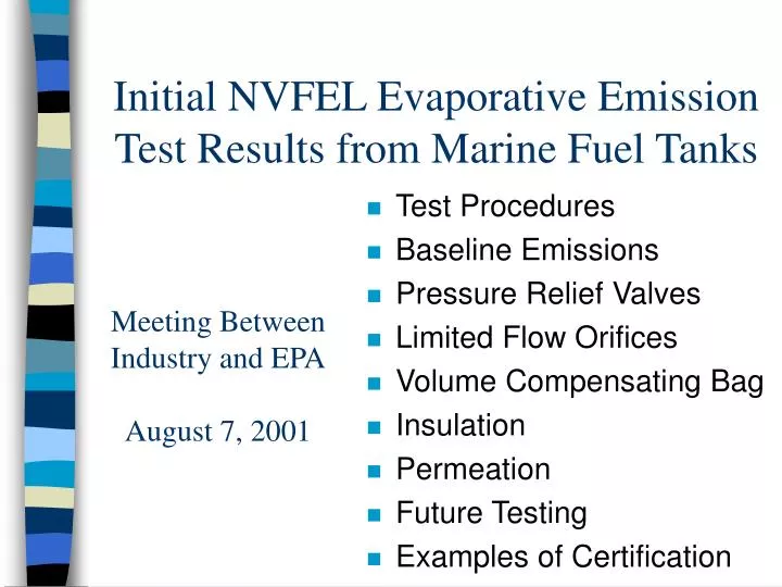
Initial NVFEL Evaporative Emission Test Results from Marine Fuel Tanks. Test Procedures Baseline Emissions Pressure Relief Valves Limited Flow Orifices Volume Compensating Bag Insulation Permeation Future Testing Examples of Certification. Meeting Between Industry and EPA August 7, 2001.

E N D
Initial NVFEL Evaporative Emission Test Results from Marine Fuel Tanks • Test Procedures • Baseline Emissions • Pressure Relief Valves • Limited Flow Orifices • Volume Compensating Bag • Insulation • Permeation • Future Testing • Examples of Certification Meeting Between Industry and EPAAugust 7, 2001
38 36 34 32 30 SHED Temperature [Celcius] 28 26 24 22 20 0 12 24 36 48 60 72 Test Time [hours] Test Procedures • 72-96 F (22-36 C) diurnal • highest of 3 days (1 day used here to save time when testing pressure strategies) • measured in SHED • certification fuel • soaking required to stabilize permeation 40% fill 9 RVP gasoline Sealed Housing for Emission Determination
Test Tanks and Baseline Emissions Moeller, blow molded, portable tank, 6 gallon 2.3 g/gal/day* *adjusted from 50% to 40% fill Inca, rotationally molded, installed tank, 23 gallon 2.5 g/gal/day Wade-Reddy Model 2.3 g/gal/day Inca, rotationally molded, installed tank, 31 gallon have not tested yet Ezell, aluminum, installed tank, 17 gallon 2.2 g/gal/day
Pressure Relief Evaporative Emission Test Data Aluminum Marine Fuel Tank 2.5 2 1.5 HC [grams/gallon/day] 1 0.5 0 0 0.5 1 1.5 2 2.5 Pressure Relief Setting [psi] Pressure Relief Valves • We modified an automotive cap with to allow us to vary the spring tension • Tests performed on aluminum fuel tank to remove the variable of permeation
Limited Flow Orifices • Looked at three orifice sizes • orifice limits rate of vapor leaving tank • this increases the pressure in the tank • 25 micron • peak delta P of 3.1 psi (did not start test at zero psi, so will retest) • 0.24 g/gal/day (probably good--appears sonic flow maintained) • 75 micron • peak pressure of 1.6 psi • 1.2 g/gal/day
Pressure, Temperature, and HC Traces Temperature Temperature Emissions Emissions Pressure (1.4 psi peak) Pressure (1.6 psi peak)
Volume Compensating Bag • Purpose of bag is to expand and contract to minimize pressure build-up • We tested a 1.5 gallon bag in 6 gallon tank • Peak pressure 0.8 psi • 0.4 g/gal/day (likely permeation) • 3 day test • Tedlar bag We are looking into other bag materials
Insulation • The purpose of the insulation is to minimize the change in temperature the fuel sees through the day • We insulated the flat plastic tank with 3 inches construction foam (R-15) and saw about a 50% reduction in emissions • We are looking into insulation that may be more appropriate for this application • Initial testing on a PWC suggests fuel temperature follows ambient temperature
Permeation • EPA testing • new blow molded tank showed low permeation • new rotationally molded tank showed higher permeation • currently soaking 3 plastic tanks to stabilize permeation rates • looking into impermeable materials/treatments • Other data • 1992 data on high-density polyethylene automotive tank • 3.0 g/day on a 22 gallon tank (0.14 g/gal/day) • 1986 USCG data on 3 rotationally molded tanks at 104 F • 18 g/day on a 12 gallon tank (1.5 g/gal/day) • 25 g/day on an 18 gallon tank (1.4 g/gal/day) • 20 g/day on an 18 gallon tank (1.1 g/gal/day) • Suggests permeation may be significant contributor to evaporative emissions
Future Testing • Collecting more data to better define a correlation between technology combinations and emissions for the purposes of design-based certification • Permeation testing (and materials investigation) • Investigate insulation further • Diurnal and LFO tests on the plastic tanks • Open to other technology options • bladder, floating vapor barrier, others?
Example of Design-Based Certification • NOTE: we are still refining our design criteria and will continue to do so as we collect more data • EXAMPLE • Baseline = 2.2 g/gal/day aluminum tank • If targeting a 50% reduction • COULD USE: • R-15 insulation with LFO to prevent convection • 1.5 psi pressure relief valve • possibly R-10 insulation with 1.0 psi pressure relief valve • (with a plastic tank, may need to use non-permeable material or target lower diurnal emissions to offset permeation)
Example of Credits Calculation for ABT • Consider averaging to a 50% reduction from 2.2 • product of ten 100 gallon tanks and five 50 gallon tanks • want to avoid new technology on 50 gallon tanks • Calculating Debits • 5 tanks X 60 gallons X (2.2-1.1 g/gal/day) = 330 • Need to make up with credits • 330 / (10 tanks X 100 gallons) = 0.33 g/gal/day • 1.1 - 0.33 = 0.77 g/gal/day • If certified 100 gallon tanks to 0.7 g/gal/day • 10 tanks X 100 gallons X (1.1-0.7 g/gal/day) = 400 • would be able to bank or trade 400 - 330 = 70 credits