Download
1 / 1
10 likes | 156 Views
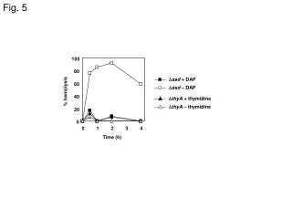
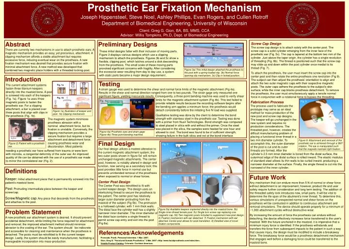
Prosthetic Ear Fixation Mechanism Joseph Hippensteel, Steve Noel, Ashley Phillips, Evan Rogers, and Cullen Rotroff Department of Biomedical Engineering, University of Wisconsin. Fig. 3a. Fig. 3c. Fig. 3b. Fig. 5. Fig. 6 . c. b. d. a. Fig. 8a. Fig. 8b. Fig. 7.

E N D
Prosthetic Ear Fixation Mechanism Joseph Hippensteel, Steve Noel, Ashley Phillips, Evan Rogers, and Cullen Rotroff Department of Biomedical Engineering, University of Wisconsin Fig. 3a Fig. 3c Fig. 3b Fig. 5 Fig. 6 c b d a Fig. 8a Fig. 8b Fig. 7 Fronczak, Frank. Personal interview. 1 Mar. 2007. Gion, Greg G. "Facial and Somato Prosthetics." 3 Mar. 2007 <http://www.facialprosthesis.com/index.htm>. Vistafix Product Catalog. Colorado: Cochlear Americas. ~1 mm References/Acknowledgements Client: Greg G. Gion, BA, BS, MMS, CCA Advisor: Willis Tompkins, Ph.D, Dept. of Biomedical Engineering Abstract There are currently two mechanisms in use to attach prosthetic ears. A magnetic mechanism provides an easy, yet precarious, attachment. A clipping mechanism affords a stable attachment but requires excessive force, inducing eventual wear on the prosthesis. A new fixation mechanism was desired that provides secure fixation with minimal attachment force. A new method was developed that combined two magnetic place holders with a threaded locking-post. Preliminary Designs Screw Cap Design The screw cap design is to attach solely with the center post. The screw cap is a solid cylinder emerging from the inner face of the prosthetic ear (Fig. 5c). The cap is tapered at the bottom two mm of the cylinder. Just above the taper origin, the cylinder has a single revolution of threading (Fig. 8b). The thread is positioned such that the screw cap may slide up and down within the post cylinder once medial to its thread (Fig. 7). To attach the prosthesis, the user must insert the screw cap into the center post and then rotate the entire prosthesis one revolution (Fig 9). The subject can then adjust the prosthesis’ orientation to align and attach the two outer magnetic caps with their respective magnetic posts. The outer caps adhere the prosthesis to the subject’s skin surface, while the inner cap blocks prosthesis detachment. To remove the prosthesis, the user must simultaneously apply a tensile normal force in conjunction with a rotational force to bypass the threading. These initial designs falter with their inclusion of moving parts. Figure 3 displays various designs which use a clipping mechanism to attach the prosthesis. Figures 3b and 3c show a flexible, clipping post, which latches around a disk descending from the prosthesis. The small scale of these moving parts provoked significant concerns with fragility. After considering the excessive wear resulting from day to day use, a system with static parts became a major design requirement . Figure 3a) This initial design attached the prosthesis to the post with a spring loaded clip. 3b) Normal force opening clip mechanism. 3c) Clip in locked position. Introduction Testing A strain gauge was used to determine the shear and normal force limits of the magnetic attachment (Fig 4a). Results in the shear and normal direction ranged from one to two pounds. The strain gage only measured one significant figure, yielding inaccurate results. Consequently, a three point bending machine was used to verify shear The current attachment systems fasten three titanium keepers directly into the mastoid bone. A post is screwed into each of the keepers (Fig. 1a). Figure 1a uses three magnetic posts to fasten the prosthetic ear. For a clipping attachment, a bar is placed over three posts that align with clips in the prosthesis (Fig. 1b). Fig. 1a limits for the magnetic attachment system (Fig 4b). This test failed to provide reliable results because the recording software begins after the bending arm applies a minimum force; the prosthesis would detach consistently before the initiating five N load was supplied. Qualitative testing was done by the client to determine the bond strength with stainless steel in the prosthetic ear. Testing was done with a primer from Nusil Technologies. Bond strength was compared to steel placed in silica with and without the primer. Once the steel was placed in the silica, the samples were heated for one hour and allowed to cool. The bond was found to be of sufficient strength, showing failure in the bulk silica and not at the bond interface. Fig. 1b Fig. 4a Fig. 9 Fabrication Process The process used to fabricate the prototype may serve as an ideal method for mass production of the new post and screw cap designs. The keeper will go unchanged in the new system and requires no production considerations. The threaded post, however, creates the difficult manufacturing problem of placing a functional inner thread in a two mm diameter cylinder. To accomplish this, the outer diameter of the post is cut and its outer threads are formed. After the Fig. 4b Figure 1a) Illustration of keeper and post. 1b) Clipping mechanism The magnetic system minimizes prosthesis abrasion with a nominal attachment force, but its fixation is unstable. Conversely, the clipping mechanism provides a secure fixation but requires a large attachment and detachment force, causing prosthesis wear and discoloration. Most patients Figure 4a) Prosthetic ears and strain gage Figure 4b) Three point bending machine Figure 9: Attachment and removal of the prosthetic ear is achieved through a 360º rotation. The ear is manipulated such that the magnets maintain tight fixation. Final Design Our final design utilizes a modest alteration to the current magnetic attachment system; the two outer posts shown in figure 5d will remain unchanged magnetic attachments. The center post, however, is notably altered in design and function, now serving as a secondary lock; this post provides little force in normal use but prevents unintended removal of the prosthesis when exposed to normal or shear forces. Figure 2) Patient with a prosthetic ear. needing a prosthetic ear have suffered from trauma or were born with microtia, a congenital deformity of the outer ear. An improved quality of life can be obtained with the use of a prosthetic ear made to mirror the contralateral ear (Fig. 2). cylinder’s 2.5 mm inner diameter is bored from the distal surface, the outermost edge of the distal surface is rolled inward. The elastic modulus of standard steel allows its thin walls to be curled inward, producing a narrower diameter at the surface. Finally, the single thread is cut into the narrowed of the inner cylinder. Definitions Keeper: Initial attachment piece that is permanently screwed into the patient’s mastoid bone. Post: Protruding intermediate piece between the keeper and screw/cap. Screw/Magnetic cap: Any piece that descends from the prosthesis and attaches to the post. Future Work Any mechanism that can endure more than 5 N of normal or shear force without detachment is an improvement; however, product life and user safety require further consideration and long term testing. The addition of the threaded safety lock introduces new, small parts. It will be vital to determine the life span of the abutment's inner thread. To determine this, various simulations of unexpected normal and shear forces on the prosthesis will be conducted in addition to continuous attachment and removal simulations. The device should operate properly for a minimum of ~1,000 attachment cycles without destructive wear. By increasing the amount of force the prosthesis can endure without detaching, the device effectively increases force transferred to the user's mastoid. With the fixture anchored in the mastoid, it is imperative that a minimum injury force is identified. If the prosthesis withstands and transfers the force from subsequent impacts to the patient in such a way that causes injury, the design must be modified to include a breakaway force. The breakaway force would be a prosthesis detachment mechanism that engages well before a damaging force could be transferred to the mastoid bone. Center Post Design The Center Post was retrofitted to fit with current keeper design. The design uses an interlocking thread to secure the prosthesis to the patient. The center post has relatively larger outer diameter protruding from the mastoid of the subject (Fig 5b). The protrusion is a hollowed cylinder, with 1 mm thick walls. The distal face the cylinder wall has a slightly narrower inner diameter. This inner diameter of the distal face contains a single thread to permit screw cap entry and exit into the post (Fig 8a). ~1 mm Figure 5a) Available keepers implanted directly into the mastoid bone. 5b) Single inner-thread female post. 5c) Single turn screw cap replacing one magnetic cap. 5d) Two magnetic posts included to supplement new post design. 6) Fixation mechanism with ear detached. 7) Fixation mechanism with ear attached. Center post allows for axial translation. 8) Detailed view of novel fixation components. Problem Statement A new prosthetic ear attachment system is desired. It should prevent accidental detachment, while limiting the force required for attachment and removal; the improved attachment method should minimize abrasion to the coating of the ear. The system should be indiscrete and accessible for cleaning and maintenance when the prosthesis is detached. The posts must be retrofitted to fit the current keeper design. Lastly, the system should be easily manufactured, facilitating a manageable incorporation into mass-production.