Download
1 / 5
60 likes | 174 Views
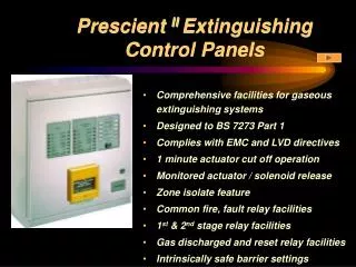
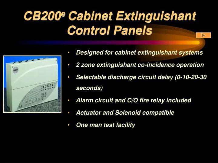
CB200 e Cabinet Extinguishant Control Panels. Designed for cabinet extinguishant systems 2 zone extinguishant co-incidence operation Selectable discharge circuit delay (0-10-20-30 seconds) Alarm circuit and C/O fire relay included Actuator and Solenoid compatible One man test facility.

E N D
CB200e Cabinet Extinguishant Control Panels • Designed for cabinet extinguishant systems • 2 zone extinguishant co-incidence operation • Selectable discharge circuit delay (0-10-20-30 seconds) • Alarm circuit and C/O fire relay included • Actuator and Solenoid compatible • One man test facility
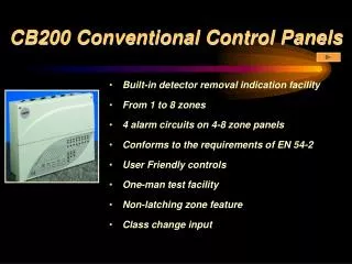
CB200 Conventional Control Panels • Earth fault monitoring • Surface or semi-flush mounting as standard • Ample termination space • Flame Resistant Polycarbonate enclosure • Complies with EMC and LVD Directives
Cabinet Specifications Semi-flush is available as standard because of the construction of the CB200 enclosure. The removable gland plate and cable entry grommets obviate the need to drill wiring holes in the panel on site. Panel dimensions are detailed in the Application Guide.
Mechanical Assembly Installer’s logo or brand image may be added. This drawing shows the ample wiring space incorporated into the CB200 panel design. PCB terminal support for mechanical reliability. Electronics are completely removable for convenience on site during fitting of the back box. There is space for two 12V 2.1AH batteries - suitable for the 24hr standby requirements on an 8 zone system.
Typical Wiring Schematic This is a typical CB200e wiring illustration as it appears in the product documentation. Apollo S60 detectors are illustrated, but the CB200e panel supports a wide variety of other manufacturers’ detectors - details in the Application Guide.