Download
1 / 10
100 likes | 364 Views
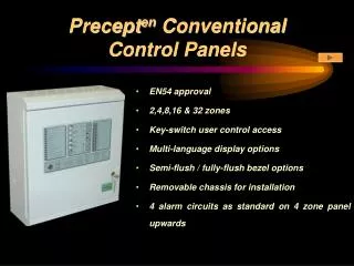
Precept Marine Conventional Control Panels. Lloyds approved to BS5839 pt 4 and ENV & ENV2 2, 4, 8, 16 and 32 zones 240V / 24V dual supply options Easily-removable chassis & removable cable-entry grommets Single man test facility

E N D
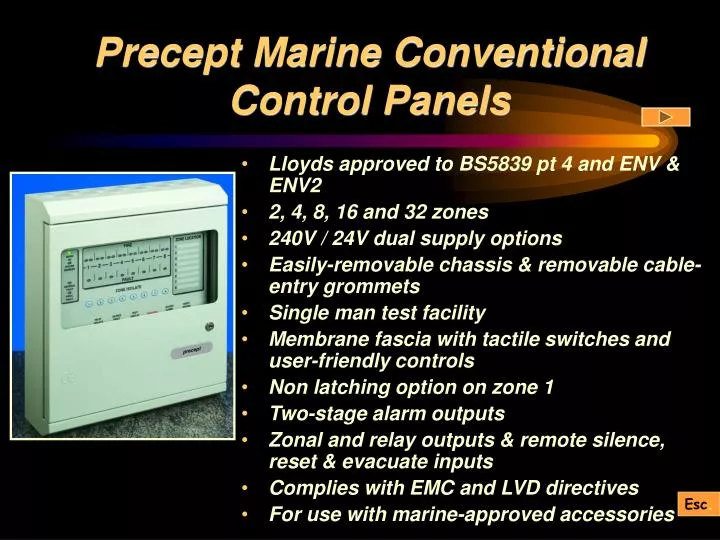
Precept Marine Conventional Control Panels • Lloyds approved to BS5839 pt 4 and ENV & ENV2 • 2, 4, 8, 16 and 32 zones • 240V / 24V dual supply options • Easily-removable chassis & removable cable-entry grommets • Single man test facility • Membrane fascia with tactile switches and user-friendly controls • Non latching option on zone 1 • Two-stage alarm outputs • Zonal and relay outputs & remote silence, reset & evacuate inputs • Complies with EMC and LVD directives • For use with marine-approved accessories Esc.
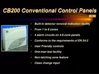
Surface Cabinets All cabinets are manufactured from sheet steel and finished in satin texture epoxy powder stove paint. Top entry grommets and rear entry knockouts are provided for ease of wiring. Cabinet colour reference is: RAL7035 Textured - Light Grey. For details of panel dimensions - see Application Guide. Esc.
Semi-flush Bezels The semi-flush bezel locates to the rear of the bevelled edge of the back box, leaving the bevelled edge and door raised out from the wall. It is finished in the same colour as the back box and is fitted by means of pinch bolts, thus avoiding the need to drill the cabinet. For details of dimensions - see Application Guide. Esc.
Fully-flush Bezels The fully-flush option is achieved by fixing a flat bezel assembly to the standard back box, replacing the standard door. Custom-made to a high quality, full-flush bezels are available in brass, stainless steel, or painted. The panel comes with assembly already fitted but can if necessary be supplied for later on-site fitting, although this may be a little time-consuming. This option not submitted to Lloyds for marine approval. Esc. For details of dimensions - see Application Guide.
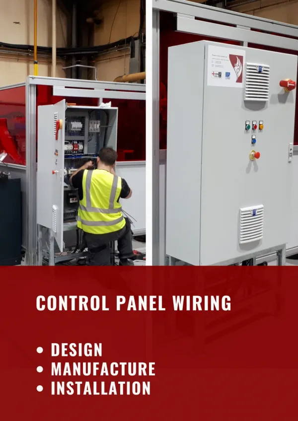
Mechanical Assembly Display and motherboard chassis are removable for ease of wall mounting. Multiple earth termination points located adjacent to cable entries. Mounting points for the Precept motherboard chassis. 24V battery set. Cabinet mounting holes. Esc.
User Controls User’s zone identification label. Lloyds approval details. The Precept Marine panel has clear, unambiguous LED indications. These single-function user controls are easy to operate. User operating instructions. Esc.
Motherboard This is the motherboard for the 2/4 zone Precept Marine panel. Motherboards for the 8 and 16 zone panels are shown in the Application Guide. The fault LEDs, fuses and DIL switch are easily accessible for the engineer when the user display board has been removed. Esc.
Typical Wiring Schematic Apollo Marine S60 detectors are illustrated, but the Precept panel supports a wide variety of other manufacturers’ detectors - details in the Application Guide. This is a typical Precept wiring illustration as it appears in the product documentation. Alarm Circuit terminals Zone terminals Repeater panel terminals. One per zone, One each for common fault, remote inputs for silence alarms, reset and evacuate, 24V and 0 V supply This option was not submitted to Lloyds for Marine Approval Battery Terminals 2 fire and 1 fault c/o relay Esc. DIL switch for panel configuration
Panel Configuration The engineer’s controls are located on the bottom of the control board. They are in the form of a 4-way DIL switch. Switch 1 Pulsing or continuous alarms Switch 2 Non-latching zone (zone 1) Does not operate fire relays (Disallowed under BS5839 pt 4) Switch 3 One man test facility Switch 4 Operates the processor fault counter in accordance with BS5839 pt 4 (8, 16, 32 zone panels only) or Disable auxiliary fire relay on evacuate (4 zone panel only) Switch 2 & 4 Shop unit specification (4 zone panel only) Esc.