Download
1 / 57
570 likes | 834 Views
CSC 341 Introduction to Computer Graphics. Graphics System. A Graphics System. Separate hardware support: relieves CPU from graphics related tasks. Raster Graphics. Image produced as a two-dimensional array (the raster ) of picture elements ( pixels ) in the frame buffer

E N D
CSC 341 Introduction to Computer Graphics Graphics System
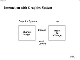
A Graphics System Separate hardware support: relieves CPU from graphics related tasks
Raster Graphics • Image produced as a two-dimensional array (the raster) of picture elements (pixels) in the frame buffer • Pixel: small area/location in the image
Frame Buffer • Two-dimensional array of pixel values • Color and other information (e.g. depth in 3D) per pixel • Not a device, a chunk of RAM memory • In early systems, frame buffer was part of system memory • Today, virtually all graphics systems have GPUs (graphics processing units) which may include the frame buffer. • Usually is implemented with special types of memory chips that enable fast redisplay of contents • A hardware device called video controller reads the frame buffer and produces the image on display
Frame Buffer • Depth: number of bits used to represent each pixel • How many colors can be represented? • 1-bit: 2 colors (black and white) • 8-bit: 256 colors (gray scale) • 24-bit: (True Color or RGB-color) • 8-bits per red, green and blue components • R,G and B combined in varying proportions • If all full intensity (255, 255, 255): you get white • If all are off (0,0,0): you get black • HDR (High dynamic range) systems • 12 or more bits per color component
Frame Buffer • Resolution: number of pixels in the frame buffer • Determines the level of detail in the image
Rasterization/Scan conversion • The processor takes specifications of graphical primitives (lines, circles, polygons) • Converts them to pixel assignments (location and color) in the frame buffer
Output Devices • Standard graphics display: raster display • Two main types: • CRT (cathode-ray tube) display • Flat-screen technologies
CRT • Consists of a screen with phosphor coating • Each pixel is illuminated for a short time (few milliseconds) when struck by an electron beam • Level of intensity can be varied to achieve gray values • Display has to be continuously refreshed to avoid flickering. • Refresh rate • Older systems: 60Hz (60 times per second) • Modern displays: 85 Hz
CRT (interlaced, noninterlaced) • Two ways of displaying pixels • Noninterlaced: row by row (scan line by scan line) • at the refresh rate • Interlaced: odd rows and even rows refreshed alternately. • Smaller refresh rate is fine. e.g. 30 times a second seems like 60 times a second.
Color CRT • Three different colored phosphors arranged in small groups • Red, Green, Blue • Three electron beams
Flat-screen Technologies • LCD (liquid crystal display) • LED (light-emitting diodes) • Plasma panels • The electric field at a location (intersection of a horizontal and a vertical wire) controls the element in the middle plate
CSC 341 Introduction to Computer Graphics Image Synthesis
Image Synthesis • In computer graphics, we form images using a process analogous to how images are formed by optical imaging systems ( Camera, Human visual system) • We will construct a model of the image formation process in optical systems that we can use to understand CG imaging systems • Basic model of viewing • A viewer holding up a synthetic camera • …to a model of the scene we wish to render
Major elements of our model: Objects and Viewer • Objects: description of the 3D scene, including • Positions, geometric structure, color, surface properties (texture, shininess, transparency) of objects • exist independent of the viewer • Viewer: description of the • location of the viewer and • properties of the synthetic camera (direction, field of view, etc.)
Geometric models • How to describe our 3D scene in a manner that can be processed by graphics programs? • Mathematically based objects are easy to model • Line : two vertices • Polygon: an ordered set of vertices • Circle: center and a point on the circle • Cube, cylinder, sphere… • ..but natural objects (hair, water, clouds) are hard
Geometric models • Simplest: Polyhedral models • Solid objects are described by their 2D boundaries • Boundaries will be constructed from flat elements: points, line segments, and planar polygonal faces • Faces: basic rendering element: In OpenGL, just a list of vertices 69,451 triangles
Geometric models • Advanced models: curved surfaces: Bezier, NURBs, subdivision surfaces, fractals, etc.
Light and light sources • Locations of light sources determine • shading of the rendered objects: which are dark which are light? • And, the location of the shadows • We assume point light sources (like sun): emit energy from a single location in all directions • Light is a form of electromagnetic energy • Over the visible spectrum • Different wavelengths are seen as different colors • To simplify: geometric optics model • light sources as emitters of energy, and have a fixed intensity • Light travels in straight lines (light ray)
Color of light • We will simply model the color of light as some combination of red, green and blue color components • What we see in an object is not its color, but the color of the light that is reflected from that object toward our eye. • If object reflects only red light but light sources emit green light, then we will see the object as ?
Color of light • We will simply model the color of light as some combination of red, green and blue color components • What we see in an object is not its color, but the color of the light that is reflected from that object toward our eye. • If object reflects only red light but light sources emit green light, then we will see the object as black!
Light propagation in the scene • Light is emitted from light sources • Strikes and illuminates objects in the scene • Interacts with object surfaces depending on surface characteristics • Being absorbed all or partially by some objects • Being reflected from or refracted through surfaces • Some light rays eventually enter our eyes • Some leave the scene—no contribution to what we see
Lighting Models • Global illumination models • Simulate this complex interaction of light and objects • Computationally expensive! • Local illumination models • Adapted by most commercial interactive graphics systems • Assume that the light rays emitted from an object come directly from light sources
Film plane, imaging plane Small hole at the center of one side: only single ray of light can enter “center of projection” Camera model: The pin-hole camera • Simple example of an optical imaging system
The pinhole camera: side view • Pointing along positive z-axis • The center of projection (COP) is at the origin (0,0,0) • Film plane located at distance d from the pinhole • Film plane is at z = -d • is projection of -d
Field of view (also called angle of view) • Assume height of the box is h • A point will be visible on the image if it lies within a cone centered at the origin with an angle • This angle is called field of view (for y). A similar formula holds for x.
Observation • The image is inverted in the projection process. • Why?
- Observation • The image is inverted in the projection process. • Why? • Because the film is behind the pinhole (center of projection)
Projection plane projector center of projection Synthetic camera model • We will move the image plane in front of the camera • The image of the point is located where the projector passes through the projection (image) plane (all projectors are rays emanating from COP)
Clipping • We must consider the limited size of the image • Recall: field of view in pinhole camera • Not all objects can be imaged onto the film • In our synthetic camera: • place a clipping window through which the viewer sees the world • given the location of the viewer/camera, the location and orientation of the projection plane, and the size of the clipping rectangle, we can determine which objects will appear in the image
World coordinate system v.s. Camera coordinate system • Observe that the projection transformation was based on the assumption that objects are represented according to the camera-centered coordinate system. • Camera moves around! • Necessary to apply a transformation to map coordinates of objects from world coordinate system to camera coordinate system
Camera specifications • We need to inform the graphics system of: • Camera location: location of the center of projection (COP) • Camera direction: what direction is the camera pointed in. • Camera orientation: what direction is “up” in the final image • Focal length: the distance from the COP to the projection plane (image plane) • Image size: clipping window size and location • Variety of ways to specify these • OpenGL asks for field of view and image aspect ratio (ratio of its width and height) rather than focal length and image size
Drivers Application Programmer’s Interface (API) • Interface between an application program and the graphics system can be specified through a set of functions in the graphics library • Programmer only sees the API, and is shielded from details of the both hardware and software implementations of the graphics library • The functions that are available through the API should match our image formation model
OpenGL is an API • Based on the synthetic-camera model • We need functions to specify (and, we have them) • Objects • Viewer/camera • Light sources • Material properties of objects
Object Specification • Most APIs support a limited set of primitives including • Points (0D object) • Line segments (1D objects) • Polygons (2D objects) • Some curves and surfaces • Quadrics • Parametric polynomials • All aredefined through locations in space or vertices
Example (OpenGL) glBegin(GL_POLYGON) glVertex3f(0.0, 0.0, 0.0); glVertex3f(0.0, 1.0, 0.0); glVertex3f(0.0, 0.0, 1.0); glEnd( ); type of object location of vertex end of object definition
Physical Approach? • Ray tracing: follow rays of light from center of projection until they either are absorbed by objects or go off to infinity • Can handle global effects • Shadows • Multiple reflections • Translucent objects • Slow
This POV-Ray picture of a beach of pebbles was generated entirely using POV (raytracer) code. No modelers were used at all. The image took 4.5 days to render on an Athlon 5600+.
Vertex Processor Clipper and primitive assembler Fragment Processor Vertices Rasterizer Pixels Practical Approach • Process objects one at a time in the order they are generated by the application • Can consider only local illumination • Pipeline architecture • All vertices go through the pipeline
Vertex Processor Clipper and primitive assembler Fragment Processor Vertices Rasterizer Pixels Vertex Processing • Carry out transformations and compute a color for each vertex • Each vertex is processed independently
Vertex Processor Clipper and primitive assembler Fragment Processor Vertices Rasterizer Pixels Transformations • Much of the work in the pipeline is in converting object representations from one coordinate system to another • Object coordinates • Camera (eye) coordinates • Screen coordinates • Every change of coordinates is equivalent to a matrix transformation • Eventually, the geometry is transformed by a perspective projection---also can be represented by matrices • Retain 3D information as long as possible in the pipeline • Thus, more general projections than we just saw