Download
1 / 22
220 likes | 308 Views
UK Stave Work. Contribution to Strip Staves Local Supports presentation at AUW. Scope. Co-curing (8 slides) - TJJ Classical Laminate Theory for co-cured face sheets CLT Calculations Manufacture & test of tokens & comparison with CLT calculations Surfaces of Co-cured Facesheets

E N D
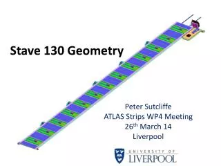
UK Stave Work Contribution to Strip Staves Local Supports presentation at AUW
Scope • Co-curing (8 slides) - TJJ • Classical Laminate Theory for co-cured face sheets • CLT Calculations • Manufacture & test of tokens & comparison with CLT calculations • Surfaces of Co-cured Facesheets • Potted history (successes & failures) • Properties of co-cured stave surfaces • Stave Assembly Tooling (3 slides) - TJJ • Tooling Design • Stavelet 6 • Glue film for honeycomb • Locking Mechanisms (6 slides) - SY • Plans for Sector Prototype (3 slides) – SY • ABCN130 Stave FEA (3 slides) - GB LSWG Meeting - Strip Stave Local Supports
Co-curing – initial trials • 7 electrical and 2 mechanical co-cures of full size tapes & 4 stavelet size • Co-cured face sheets can be sucked onto vacuum jig, although residual curvature difficult to control along edge. • In autoclave gluing edge of tape needs to be protected from glue creep with tape. • Larger residual twist in electrical tapes (thicker aluminium) • Dimensional changes measured • Concerns over face sheet integrity • Concerns over surface ‘roughness’ Autoclave cures for 0.5mm stavelet on CF Tooling Press cures for full length stave Autoclave cures for full length stave LSWG Meeting - Strip Stave Local Supports
Ripples, Defects & De-laminations • Ripples in Plank 5 tapes seen after few 10’s of thermal cycles • Issue with tape manufacture? • Defects • Detailed investigations of used/unused face sheets reveal large variety of surface ‘defects’ • De-laminations (within CF face sheet) • 125C/4h co-cured K13D2U/RS3 face sheets (US tapes) • De-laminations after 1 hour at -45C • Focus on theoretical calculations / FEA modelling of stresses in co-cured structures together with a prototyping plan for verification LSWG Meeting - Strip Stave Local Supports
Surface Defects • Likely that these are from the process • CFRP face sheets are free from defects • Process (based on US technique) • Abrade tape with Scotch-brite / ethanol • Bake out tape over night at 110C • Lay up 0/90 & compact for 30’ • Add top 0 layer & compact for 30’ • Remove tape from oven, allow to cool & add to stack. • Add release ply, silicone rubber pad & caul plate, compact for 1hr • Transfer to autoclave & cure at 120 deg C for 3 hours; release autoclave pressure & allow autoclave to cool over night with vacuum pump on; • Surface Profiles • Initial 2D measurements using needle-probe • New sample better than plank 5 but worse than plank 4 LSWG Meeting - Strip Stave Local Supports
Classical Laminate Theory Applied to Co-cured face sheet (120C cure) • Model • Assume copper has little effect • Aluminium thickness = 0.05mm • Aluminium modulus = 69MPa • Classical Laminate Theory • In general, the loads [N] and moments [M], expressed as column vectors, acting on a laminate can be related to the strains () and mid-plane curvatures () through the matrix equation; • [A],[B] and [D] are 3x3 matrices called the extensional, coupling and bending stiffness matrices respectively. • Extensional matrix [A] relates the resultant in-plane forces to the in-plane strains • Bending matrix [D] relates the resultant bending moments to the laminate curvatures. • Coupling matrix [B] couples the resultant forces and moments to mid-plane strains and curvatures. • Solving the matrix equations gives the strains () and mid-plane curvatures () • Curvature seen in non-zero kappa values LSWG Meeting - Strip Stave Local Supports
Experimental Measurements 90/0/90 + tape 0/90/0 + tape Measure strain on top and bottom surfaces of 0/90/0+tape laminate vs temperature and compare with prediction from CLT • Plot of height vsx2(where x is the position along the length) will have a slope of /2. • 0/90 K3.6 (5.8) • 0/90/0+tape K 9.2 (11.5) 0 0/90 0/90/0 LSWG Meeting - Strip Stave Local Supports
Effect of Aluminium Yield Strength • Use CLT to predict stresses for a given temperature change • Apply external moments to keep laminate flat & simulate sandwich construction • Calculate using EXCEL • Split matrix summations into constant part and aluminium modulus dependent part • For a given temperature change • Use CLT to calculate stresses in each layer with suitable external moments applied to keep laminate flat • Sum to give total stress in aluminium layer • Use aluminium stress and Ramberg-Osgood formula to calculate aluminium modulus for next temperature change LSWG Meeting - Strip Stave Local Supports
Stresses in CF Layers vs. Al yield Strength Unless the aluminium yield strength is very high, co-cured face sheets should be robust against thermal cycling down to operating temperature with a reasonable safety margin. LSWG Meeting - Strip Stave Local Supports
Co-curing Conclusions • Historically we’ve had mixed experience • De-laminations • Some co-cures show signs of de-lamination – but not all • Surface Defects • Some co-cures have very smooth surfaces – others do not • Likely cause (of both!) is the lamination process • Take on-board expertise in US (LBNL September meeting) in particular; • Bake-out of bus tape • Compactification during lay-up • 1st sample looks encouraging LSWG Meeting - Strip Stave Local Supports
Stave Assembly Tooling • Programme to develop low(er) mass, more stable stave assembly tooling • Start with CF sandwich version of stavelet tooling to prove manufacturing techniques • 1.5mm CF skins on 7mm Nomex honeycomb • Embedded vacuum channel • FR4 vacuum channel network • ~ 380 2mm dia. vacuum holes • Global flatness measured on CMM • 60% within +/- 10mictons • Surface roughness measured using needle probe • Ra ~ 1.5microns +0.03mm LSWG Meeting - Strip Stave Local Supports
Stave Version • Combination of the 2nd Liverpool stavelet jig and the requirements for the Oxford stave assembly tooling for individual components • Parts in fabrication at Liverpool & Oxford • Hope to complete by end of 2011 LSWG Meeting - Strip Stave Local Supports
Stavelet 6 • Conventional build + • New tooling • 80C cure glue film for honeycomb (~ 60% area removed using pattern cutter) LSWG Meeting - Strip Stave Local Supports
UK Locking Mechanism Update Previous locking mechanism The UK stave mounting design is based on the edge mounting and end insertion. Once inserted into position, the stave is fixed at the Z=0.0 position at two locations, and along the long edge at 5 locations. The fixing condition at the Z=0.0 is fully locked on one side and guided on the other, and those along the long edge are “locked” in a manner that when the mounting points are locked, the stave is pressed against a pre-determined datum faces that guarantees the azimuth and radial positions of the stave, but allows differential thermal movement between the stave and the cylinder in the Z-direction. 14 LSWG Meeting - Strip Stave Local Supports
Motivation of new locking mechanism • Number of parts reduced from 6 to 3. Material volumes very similar. • The existing design works when stave tilting angle at 16 deg. • Can not fit into the space envelope when the stave tilting angle at 10deg. • Further improvement of the existing design from the following aspects: • Reduce the number of parts • Reduce the number of reference faces to avoid over constraint • Further improvement on end insertion • Fit into the space envelop at stave tilting angle of 10o. LSWG Meeting - Strip Stave Local Supports
Locking and Reference Faces Reference faces Reference faces Cam (retracted) 2 Reference faces Unlocked, typ gap 0.2 Over centre dimples 4 Guide Rail interface Locked, 0 gap LSWG Meeting - Strip Stave Local Supports
Slide in guide rails using features in mounting brackets to locate. Rotate guide rails so that the rails + the mounting bracket corms a continuous channel. Secure by inserting rode (green) Stave slides along channels via the locking points. When the stave is in the correct location, the stave is locked in Z, the cams are actuated and the guide rails removed. End insertion and tooling concept Note: Guide rails are only used during insertion of the stave, and are fully withdrawn once insertion has finished.
3D illustration LSWG Meeting - Strip Stave Local Supports
Being supported at various rotational positions LSWG Meeting - Strip Stave Local Supports
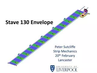
Innermost layer Geometry and Stave Envelope Space envelope Clearance within space envelope (for 10o stave tilt angle) including that for the rotation of the guide rails. LSWG Meeting - Strip Stave Local Supports
Remarks • The new locking mechanism design fits into the revised space envelope when the stave tilt angle is 10 • A prototype of the new locking mechanism has been made out of PEEK, and is working as expected. • This new design allows end insertion to be carried out during installation as well as stave removal should this proves necessary after installation; • Plan to build a stave sector prototype with 4 staves to demonstrate the end insertion and positioning of the locking mechanism. The design and construction of this setup is now underway and we aim to get this done by the early next year. LSWG Meeting - Strip Stave Local Supports
Stave Sector Prototype some tooling balls will be fitted on various position on the sector for easy survey. Carbon Fibre sandwich sector base FEA carried out to check the interlink rigidity. LSWG Meeting - Strip Stave Local Supports