Download
1 / 15
150 likes | 315 Views
HPD Performance in the RICH Detectors of the LHCb. Young Min Kim University of Edinburgh IoP HEPP Conference – April 2009. LHCb and the RICH Sub-Detectors. Momentum-Polar Angle plot of simulated B d -> events, showing regions that the RICH detectors will cover.

E N D
HPD Performance in the RICH Detectors of the LHCb Young Min Kim University of Edinburgh IoP HEPP Conference – April 2009
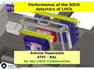
LHCb and the RICH Sub-Detectors Momentum-Polar Angle plot of simulated Bd-> events, showing regions that the RICH detectors will cover LHCb Sideview Schematic, with RICH1 and RICH2 circled in red and orange • Used for Particle Identification: the radius of the ring of Cherenkov photons created by charged particles can be used to infer its velocity. • 2 Ring Imaging Cherenkov (RICH) detectors to cover different momentum and polar angle ranges.
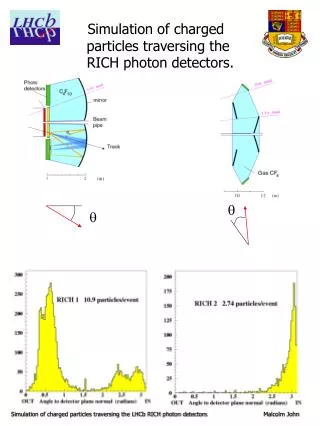
RICH1 Schematic • Charged particle (e.g. ) passes through 2 different radiators • Different refractive indices for wider coverage of photon angles • Cherenkov photons collected by mirrors onto photon detector panels • Data from both panels put together to reconstruct the Cherenkov ring
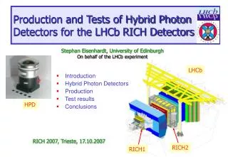
Eyes of the RICH: the HPDs • Hybrid Photon-Detectors (HPDs) are used in the RICH • Uses the photo-electric effect • Bi-alkali photocathode deposited on back of quartz window • HPD is vacuum sealed • Electric field focuses photoelectrons to silicon sensor • Sensor is bump-bonded to readout chip • Readout speed matched to 25ns clock • 8192 pixels of size 500m x 62.5m
Photos of HPDs Single HPD. Ruler is 10cm long Panel of HPDs inside RICH
HPD Testing • 550 HPDs needed to be independently tested and categorised. • Photon Detector Test Facilities (PDTF) were set up in Scotland to do this: 2 stations each at Edinburgh and Glasgow • The Quantum Efficiency (QE) of a subsample of the HPDs were measured. • QE = Overall probability an incoming photon produces a detected photoelectron.
QE Results • Quantum Efficiency (QE) improved over the manufacturing process: • improve S/B ratio from QE
QE Results II Bad Vacuum Typical • Left: a typical HPD’s QE results. Close agreement with manufacturer’s measurements • Right: an early prototype HPD which shows Ion Feedback due to degraded vacuum
Result of Bad HPD Vacuum:Ion Feedback (IFB) • Vacuum degradation: gas particles inside HPD body • Photoelectrons ionise these gas particles • Gas ions drift back to photocathode by electric fields • Many secondary electrons released when gas ions reach photocathode • These secondary electrons reach the silicon sensor after a delay, typically 250ns after the primary photoelectron • In very bad cases, chain reaction occurs as these secondary electrons also ionise gas particles
Monitoring HPDs Mounted in RICH • Once shipped to CERN, HPDs mounted into columns and installed in RICH • RICH1 has 196 HPDs • RICH2 has 288 HPDs • The commissioned RICH detectors go through test runs, with a laser light source RICH2 Column, fitted with 16 HPDs
RICH2 HPD Pixel Hitmap • Many test runs carried out over the months • Continuous Wave (CW) Laser used • This hitmap is for RICH2’s 288 HPDs • 2.36 million pixels • 3 million data readout events • Hitmap shows how many hits each individual pixel received • Most HPDs read out fine, but some are bad due to vacuum degradation RICH2 Detector Plane
Glowing HPDs • HPDs producing light at high vacuum degradation • 5% Ion Feedback (IFB) threshold used as warning flag for HPDs that may start glowing Glow Light
IFB Development Over Time H542001 IFBcw Typical • We needed to know when to expect HPDs to start glowing so we can prepare replacements in advance • IFB was monitored over several months • The IFB development of the majority fit a linear model. This made IFB extrapolations possible 0.1% Days H525014 IFBcw Bad Vacuum start of glowing 1% Position in RICH2: A0-5 Days
Projected IFB in 5 Years’ Time RICH1 • RICH detectors need good HPDs until 2015 • Extrapolated IFB shows only a minority of HPDs will be at risk of glowing • Glowing HPDs are replaced by spares while they get repaired IFBcw IFBcw RICH2
Conclusions • We have commissioned both RICH detectors and most of our HPDs are working fine • Quantum Efficiencies of HPDs exceeded specifications and gradually improved during manufacturing process • HPDs have good performance in RICH detector test runs with laser light source • Causes of higher rates of vacuum degradation in a minority of HPDs currently being investigated