Download
1 / 30
300 likes | 311 Views
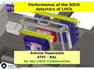
The RICH detectors of LHCb; Description and Operation. Antonis Papanestis On behalf of the LHCb RICH collaboration. 1. Outline. The LHCb experiment The LHCb RICH detectors Description Construction and installation Operation Alignment and Calibration Conclusions. 2. The LHCb experiment.

E N D
The RICH detectors of LHCb;Description and Operation Antonis Papanestis On behalf of the LHCb RICH collaboration 1
Outline • The LHCb experiment • The LHCb RICH detectors • Description • Construction and installation • Operation • Alignment and Calibration • Conclusions 2
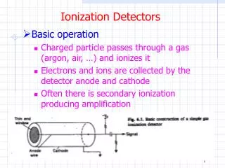
The LHCb experiment Probing New Physics in CP violation and rare decays of b and c quarks Single arm spectrometer with: • Excellent vertexing • Excellent PID • Efficient trigger and tracking RICH 2 RICH 1 3
LHCb event 23 sep 2010 19:49:24 Run 79646 Event 143858637 4
LHCb luminosity LHCb was designed to run at μ~0.5 and nb~2600 ⇒ Linst~2×1032cm-2s-1 In 2012 LHCb runs with μ~1.7 and nb~1300 ⇒ Linst~4×1032cm-2s-1 2010 data 2011 data 2012 data μ=2.7 design μ=0.4 Automatic luminosity levelling 2 fb-1 1 fb-1 5
The LHCb RICH detectors RICH 2 RICH 1 2 Detectors 3 Radiators Acceptance 15-120 mrad Acceptance 25-300 mrad Side view Top view 300 mrad ~7 m 120 mrad Spherical mirrors Flat mirrors CF4 gas Note Scale Difference 6
RICH 1Tight space, low mass Photon detector plane 14 by 7 Hybrid Photon Detectors (HPDs) 4m Spherical Mirrors Lightweight carbon fibre mirrors 1.5% radiation length VELO Exit Window 2mm aluminium.. Sealed to gas enclosure. No RICH entrance window. RICH1 Exit Window Carbon fibre & PMMI foam Sealed direct to the beampipe. 8
Carbon fibre mirrors and Aerogel Aerogel is inside a gas tight box flushed with CO2 to avoid performance degradation from exposure to C4F10 9
8m RICH 2Huge volume, very precise Flat Mirrors each made from 20 square glass segments Spherical Mirrors each made from 21 glass hexagonal segments Magnetic Shields protect the HPD planes HPD planes of 9 by 16 HPDs RICH2 entrance / exit windows carbon fibre and foam sandwich Gas Enclosure Contains CF4 gas radiator and the optical system 10
Photon Detectors Main features of Pixel-HPD: Quartzwindow with thin S20 pK Cross-focussing optics (tetrodestructure): • De-magnification by ~5 • Active diameter 75mm 484 tubes for overall RICH system • Up to 20 kV operating voltage (~5000 e–[eq. Si]) 3232 pixel sensor array (500m500m each) Encapsulated binary electronics readout chip Schematic view See talk by Stephan Eisenhardt 12
The readout chain • All HPDs arranged in columns with ancillary front-end electronics • LV & HV boards power the HPDs • “Level-0” board passes triggered data to the “Level-1” off-detector board via an ~100m optical link • Level-1 board receives and zero-suppresses the data and passes to the DAQ 13 HPD column assembly
Protection during Injection A failed injection can shower the detectors with secondary particles. 144 nominal bunches striking the collimators 300 m upstream of LHCb. Photon detectors are switched OFF during Injection. Fully ON ready for data taking in 15 min. 14
CF4 ScintillationQuenched using CO2 “Extra” photons from scintillation were saturating data bandwidth Inefficiency is calculated from lab measurements 15
Alignment & Calibration • Alignment: • Silicon sensors • Magnetic field corrections • HPD alignment • Mirror alignment • Detector alignment (in the LHCb coordinate system) • Calibration: • Time alignment (should be constant). • Refractive index (from Cherenkov angle). See talk by Clara Matteuzzi 17
HPDs in magnetic field Magnetic distortions Test pattern measurements with locally shielded HPD 0 G B║ 30 G B┴ 50 G 18
RICH1 RICH 1 MDCS Correcting for the magnetic distortions Pixels (0.5 mm) 19
RICH 2 MDCS A temporary setup, using commercial projector was used in 2008 to project a static, reproducible grid of light spots onto the photon detector plane, The raw spot images were analysed to calculate the centre of gravity for precision comparison between measurements: 20
Time alignment Both RICH detectors are time aligned to less than 1 ns 21
Anode image fitting • Position of the photocathode image on the anode can change. • Anode images are cleaned and a Sobel filter is used to detect the edge. • Automated procedure, updates the position of the photo-cathode centre in Conditions Database 22
Conclusions • LHCb recorded 3 fb-1 so far, running at twice the design luminosity, at 90% efficiency, producing a number of world first and world best measurements. • The LHCb RICH detectors are an integral part of LHCb, operating in a challenging high multiplicity environment, working at conditions well above the original specifications. • The outstanding performance of the RICH system is achieved with an excellent and stable optical system and very low noise photon detectors, together with the highly automated alignment and calibration processes. 25
The END 26