Download
1 / 29
290 likes | 292 Views
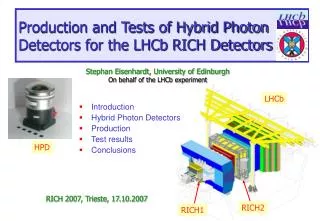
LHCb Rich Detectors Control and High Voltage Systems. Mario Sannino On behalf of LHCb RICH Group. Rich 2007 Trieste 19.10.2007. LHCb Rich Detectors Control and High Voltage Systems. An overview of the Monitoring/Control System of the RICH Detectors in LHCb experiment will be presented

E N D
LHCb Rich Detectors Control and High Voltage Systems Mario Sannino On behalf of LHCb RICH Group Rich 2007 Trieste 19.10.2007 Rich 2007 Trieste 19.10.2007
LHCb Rich Detectors Control and High Voltage Systems • An overview of the Monitoring/Control System of the RICH Detectors in LHCb experiment will be presented • In particular this talk will concentrate on the Monitoring/Control methods fundamental for an efficient RICH Detector operation Rich 2007 Trieste 19.10.2007
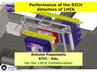
Spherical mirrors Flat mirrors Beam pipe Photon detector housing and shielding LHCb RICH detectors Mirror Support Panel Spherical Mirror 8m Support Structure 4m Flat Mirror RICH2: 17-100 GeV/c Central Tube RICH1: 2-60 GeV/c Photon detector housing and magnetic shielding Rich 2007 Trieste 19.10.2007
Fundamentalfor an efficient RICH operation are: • Low Voltage and High Voltage control and monitoring • environment monitoring (temperature, pressure, humidity) • radiatorgas quality monitoring • mechanical stability (mirror alignment) monitoring • detector safety This is achieved by means of the DCS (Detector Control System), in charge of detector operation, i.e. Monitoring, Control and low level Safety. DCS will also automatically recover simple problems and restore normal operating conditions. Rich 2007 Trieste 19.10.2007
LHCb Partial Simplified view ECS = Experiment Control System DCS =DetectorControlSystem DSS = Detector Safety System Rich 2007 Trieste 19.10.2007
ECS/DCS Hardware ImplementationBoard level electronics • Electronics in barracks (out of Radiation Area) • Front-ends, Readout Units, • Timing and Fast Control components, • VHV Control • Credit Card PC’s Ethernet interfaced acting as an embedded controller generating needed I2C, JTAG and a parallel bus by means of a proper “glue” logic (Glue Card) • 66 85 12 mm3 • Pentium Compatible CPU • Linux/DIM I2C JTAG Bus S I2C JTAG Bus S Ethernet I2C JTAG Bus S Credit Card PC Glue-Card
ECS/DCS Hardware Implementation Front-End Electronics • In Radiation Areas needed I2C and JTAG generated by the busses • SPECS • Serial Protocol (inspired from Atlas) • 10Mb/s • Slave is radiation tolerant • CANprotocol (0.5Mb/s) in charge of controlling ELMB’s (used for Environmental and Voltage monitoring) S I2C JTAG S I2C JTAG SPECS CAN S I2C JTAG I M
Implementation of LHCb RICH Detectors Monitoring Rich 2 ECSsupervisor PC Supervisory Level (Control Room) PVSS II Control Level (Counting Room) Rich2 Voltage and Environment Monitoring Rich2 Power Supplies Control Rich2 VHV Power Supplies Control Quality Monitoring Device/Sensor Level ELMBs PLC Other (DSS, …) Radiation Area • Gas Quality • Alignment Sensors T, P,H Voltages LV, HV, L1 HPD Planes Temp. VHV Environmental Monitoring Voltage Monitoring Power Supplies Safety Interlocks Power Supplies Quality Monitoring • Environmental monitoring is implemented by means of resistive transducers ( • (PT100 &1000 for T, Diaphgram Sensors for Pressure, HMX2000-HT sensors for Humidity) • ELMBs are CAN controlled monitoring boards with 64 analog input channel 16 bit res. Rich 2007 Trieste 19.10.2007
Environmental Parameters Monitoring HPD box temperature Environmental Parameters PVSS II typical Monitoring Panels HPD box humidity RICH2 CF4 radiator temperature <- 5 days -> Rich 2007 Trieste 19.10.2007
Gas Radiator quality Monitoring (I) The Gas Purity is critical to a reliable working of the RICH Detectors. Speed of sound in gases depends on molecular weight: and so it can be exploited to quickly spot gas pollution. g = cp/cv is the ratio of specific heats R is the constant of gases T is the absolute temperature M the molecular weight Effect of air contamination Rich 2007 Trieste 19.10.2007
Gas quality Monitoring (II) Speed of sound is monitored by measuring the time that a sound pulse takes to propagate back and forth along a gas column after having been reflected by the opposite wall. 2 such Systems on each Rich One on gas inlet A second on gas outlet The heart of the system is an electrostatic transducer acting both as source and detector. The time measurement is performed by a National Instrument Acquisition Board with an internal counter running at 20 MHz so, with a resolution of 50 ns This is enough to detect a 1% CO2 pollution in C4F10 (see graph) 10
CCDs HPD Plane Flat Mirror Spherical Mirror Common Mounting Plate Beam Splitter Mirror Focuser Laser alignment monitoring system (I) Mirror position must be known with good precision and any change of it must be tracked as accurately as possible. A 0.1 mrad resolution is required as seed for final software alignment. An optical system has been implemented in order to monitor changes in selected mirror segments. Working principle: Laser with optical fibre coupling system delivers light to 16 fibres in Rich2 and 8 fibres in Rich1. Each fibre has a focusing unit at its end and is focused onto a mirror segment (4 spherical and 4 flat per side). A beam splitter provides a reference beam for each fibre focused on a CCD camera on roof of detector. A second beam reaches the mirror and then is reflected back to the CCD camera. Rich 2007 Trieste 19.10.2007
Laser alignment monitoring system (II) Can track difference between two beam spots, even if spots move: Accuracy of monitoring better than0.01 mrads.
VHV Power Supplies Control System (I) In LHCb Rich a custom VHV system for the HPD field supply was needed due to the fact that no commercial power supply satisfied our requirements: • 20KV output • Ethernet network interface compatible with CERN standard • Reliable and modern (maintenance!) • Architecture of the system • The system is composed by 3 items: • Commercial HV unit: One unit for each column. • Motherboard with local intelligence • One unit for each Detector • 3.Control Board with optical isolation (avoid Gnd loops) • One unit for each column Rich 2007 Trieste 19.10.2007
VHV Power Supplies Control System (II) Rich 2007 Trieste 19.10.2007
VHV Power Supplies Control System (III) • Commercial HV unit: ISEG CPn 200 504 10-K • 0-20 KV output • Imax = 0.5 mA • Remote control: analog input 0-10V • Possibility to set Imax with a control voltage • Monitoring of Vout and Iout • Reasonably priced • Custom version possible (2 output cable to cope with the HV splitter) Rich 2007 Trieste 19.10.2007
VHV Power Supplies Control System (IV) The Motherboard • Standard VME size card ( 6U type) • Local Intelligence: Credit Card PC (CCPC) • Ethernet interface built-in • CERN fully supported • Easily interfaced with external devices by means of the so called Glue Card. Connections with Control Boards implemented by means of 4 I2C buses (from the Gluecard) • Interlock Management and distribution entirely controlled by a small FPGA
VHV Power Supplies Control System (V) Control Board ISEG VHV Power Supply 17
VHV Power Supplies Stability (19540 ± 18) V A stability of the ouput voltage under load of the order of 1 ‰ is achieved as can be seen from the aside plots where a voltage of 19540 Vwith20 V RMS max is reported for a sample channel
Conclusions In LHCb a complex system in order to control and monitor the Rich Detectors was designed and implemented • All the needed parameters are monitored • Environmental • Pressure • Temperature • Humidity • Quality • Mirror Alignment • Gas Quality • A new VHV Power Supply System completely automatized and remotely controlled was developed and is now working with good performances • In case of simple problems the system is able to recover them restoring normal operations conditions • In case of hard safety problems the system is able to interlock the detector putting it in a safe state. Rich 2007 Trieste 19.10.2007
Spare Slides Rich 2007 Trieste 19.10.2007
RICH1: 2-60 GeV/c LHCb RICH detectors RICH2: 17-100 GeV/c Rich 2007 Trieste 19.10.2007
Monitoring • HPD enclosure: • Air temperature (2 pt100). • Humidity. • Up to 16 temperatures (hot spots) per column (pt1000). • High Voltage (6 voltages per column). • Cooling pressure. • Light level. • Voltages and currents (from the power supplies). • Temperature in RICH2 radiator: • 20 pt100 in gas volume. • Relative pressure (no gas yet). Rich 2007 Trieste 19.10.2007
Environmental Parameters Monitoring (II) RICH2 CF4 radiator temperature Environmental Parameters PVSS II Monitoring Panel Rich 2007 Trieste 19.10.2007
Safety • PVSS • Per column: • Any high column temperature will switch off the particular column. • Power supplies will trip at over current. • HV disable if over-current, over/under-voltage, monitoring problem. • Per HPD enclosure: • High ambient temperature will switch off whole side. • Loss of cooling will switch off whole side. • DSS • Any alarm switches off whole RICH detector. • Ambient temperature sensors. • Chain of thermo-switches (1 per column). • Rack related alarms. • Light level • Disables High voltage. Rich 2007 Trieste 19.10.2007
An embedded PC is still not a board-controller • For controlling, configuring and monitoring FPGAs and ASICS need rather I2C, JTAG Traditional PC interfaces: PCI, ISA, parallel port, USB not very suitable for chip-control • and a high-speed, “simple”, long distance parallel bus • Need some small adapter or “glue-”logic • The LHCb glue-cardhas an I2C / FPGA controller + a fast local bus generated from a PLX 9030 all controlled by an FPGA. (For details see: F. Fontanelli, B. Jost, G.Mini`, N. Neufeld, R. Abdel-Rahman, K. Rolli, M. Sannino 10th ICALEPS Conference Geneva 2005 PO2.062) Rich 2007 Trieste 19.10.2007
Laser alignment monitoring system (Ib) • Analysis software needs to recover centre position of reference and reflected beam with optimum accuracy and robustness. • Beam not perfectly Gaussian so fitting method is not appropriate for a variety of differently shaped beams • Adopt a different approach using techniques borrowed from image processing. • Adopt a multi stage approach: • Smoothing filter • Edge enhancement • Sobel mask edge detection • Hough transform accumulator to determine centre of beam • Anomaly cut for spurious centre elimination • Centre spot location mask • Weighted average for centre determination. Rich 2007 Trieste 19.10.2007
Voltages Monitoring Rich Voltages Monitoring Panel Rich 2007 Trieste 19.10.2007