Download
1 / 11
110 likes | 224 Views
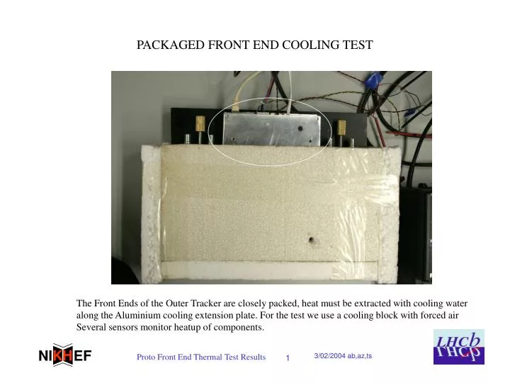
PACKAGED FRONT END COOLING TEST. The Front Ends of the Outer Tracker are closely packed, heat must be extracted with cooling water along the Aluminium cooling extension plate. For the test we use a cooling block with forced air Several sensors monitor heatup of components.

E N D
PACKAGED FRONT END COOLING TEST The Front Ends of the Outer Tracker are closely packed, heat must be extracted with cooling water along the Aluminium cooling extension plate. For the test we use a cooling block with forced air Several sensors monitor heatup of components.
ASDBLR AS TEMPERATURE SENSOR ~750mV ~1.8mV/C We use a dummy input diode as temperature sensor (Not callibrated yet)
NTC 5K on Copper Surface Close to ASDBLR Each oard has a sensor Connection point
OTIS NTC NTC UNDER OTIS ON OPOSITE SIDE
RESULTS AFTER SETTLING H K NI EF 35 C Otis52 C ASDBLR NTC on copper 42C ASDBLRInput Diode43C Proto Outer Tracker Front-End Tests 9
FIRST IMPRESSION FROM PAPER RECORDERS AFTER POWER SWITCH ON OTIS Copper NTC 52C 50 17C 45 RED ASDBLR NTC ON Copper Board SURFACE 42C ASDBLR 40 BLUE ASDBLR DIODE ~43C 8C BASEPLATE THERMOMETER 35C 35 COOLING BASE 30 REMARKS: 1.forced air cooling base with regulators, shifts 10C 2.ASDBLR steps up 5C in 2 minutes, then settles to 7C above plate 3. OTIS settles 17C above cooling flap part of baseplate 25 1 2 3 6 12 Hours t=0 >power on
FIRST CONCLUSIONS The ASDBLR has low temperature rise thanks to strong thermal coupling trough PCB Delta T=7 degrees C The maximum delta T is 17 degrees C for the Otis chip The regulators are mounted directly on the cooling plate , no internal sensor available, but adequate cooling is ok.