Download
1 / 17
170 likes | 211 Views
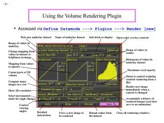
Explore hardware texture mapping methods for rendering volume data, texture-mapped polygons, and 2D images in 3D space. Understand slicing planes, object-space vs. image-space methods, and the impact on rendering quality and artifacts.

E N D
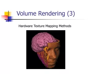
Volume Rendering (3) Hardware Texture Mapping Methods
Texture Mapping + Textured-mapped polygon 2D image 2D polygon
(0,1) (1,1) (0,0) (1,0) Texture Mapping (2) (0,0.5) (0.5,0.5) (0,0) (0.5,0) assign the texture coordinates to each polygon to establish the mapping Each texel has 2D coordinates assigned to it.
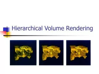
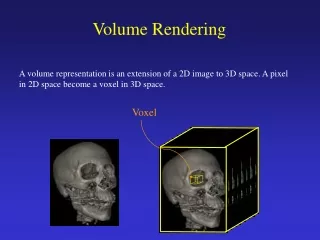
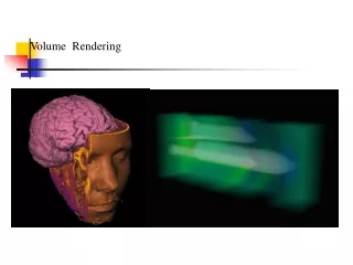
y z Tex. Mapping for Volume Rendering Remember ray casting …
z y x Texture based volume rendering • Render each xz slice in the volume as a texture-mapped polygon • The texture contains RGBA (color and opacity) • The polygons are drawn from back to front
Texture based volume rendering Algorithm: (using 2D texture mapping hardware) Turn off the z-buffer; Enable blending For (each slice from back to front) { - Load the 2D slice of data into texture memory - Create a polygon corresponding to the slice - Assign texture coordinates to four corners of the polygon - Render and composite the polygon (use OpenGL alpha blending) }
y z Some Considerations… (2) What if we change the viewing position? That is okay, we just change the eye position (or rotate the polygons and re-render), Until …
y z Some Considerations… (3) Until … You are not going to see anything this way … This is because the view direction now is Parallel to the slice planes What do we do?
y z Some Considerations… (4) • What do we do? • Change the orientation of slicing planes • Now the slice polygons are parallel to • XZ plane in the object space • We need to reorganize the input textures • Reorganize the textures on the fly is too • time consuming. We might want to • prepare this texture sets beforehand
y z Some Considerations… (5) When do we need to change the slicing planes? ? When the major component of view vector changes from z to y
Some Considerations… (6) Major component of view vector? Normalized view vector (x,y,z) -> get the maximum one If x: then the slicing planes are parallel to yz plane If y: then the slicing planes are parallel to xz plane If z: then the slicing planes are parallel to xy plane -> This is called (object-space) axis-aligned method. Therefore, we need to keep three copies of data around all the time!!
y z Problem Object-space axis-alighed method can create artifact: Poping Effect V = 44.999 V = 45.0001 There is a sudden change of viewing slicing (and thus the sampling rate) then the view vector transits from one major direction to another. The change in the result image intensity can be quite visible
Solution Use Image-space axis-aligned slicing plane: the slicing planes are always parallel to the view plane
Image-Space Axis-Aligned Arbitrary slicing through the volume and texture mapping capabilities are needed - Arbitrary slicing: this can be computed using software in real time This is basically polygon-volume clipping
Image-Space Axis-Aligned (2) Texture mapping to the arbitrary slices This requires 3D Solid texture mapping Input texture: A bunch of slices (volume) Depending on the position of the polygon, appropriate textures are mapped to the polygon.
(r2,s2,t2) (r3,s3,t3) (r1,s1,t1) (r0,s0,t0) Solid (3D) Texture Mapping Now the input texture space is 3D Texture coordinates (r,s) -> (r,s,t) (0,1,1) (1,1,1) (0,1,0) (1,1,0) (1,0,0) (0,0,0)
Pros and Cons Advantages: - Higher quality - No popping effect Disadvantages: - Need to compute the slicing planes for every view angle - 3D texture mapping is not supported by most of graphics hardware except high end ones (althugh people are working on it right now. ATI Radeon card, $250, starts to support it. Both 2D or 3D hardware texture mapping methods can not compute Shading on the fly. The input textures have to be pre-shaded.