Download
1 / 26
260 likes | 266 Views
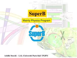
SuperB. SuperB Injection System. R. Boni, INFN-LNF - on behalf of the “Injector Study Group”. SuperB Workshop, LAL-Orsay, Febr. 2009. R. Boni, S. Guiducci, P. Raimondi, INFN-LNF. To follow … the Biodola-Meeting ( june 2008 ) and the LNF-Mini-Mac ( july 2008 ).

E N D
SuperB SuperBInjection System R. Boni, INFN-LNF - on behalf of the “Injector Study Group” SuperB Workshop, LAL-Orsay, Febr. 2009 R. Boni, S. Guiducci, P. Raimondi, INFN-LNF
To follow … the Biodola-Meeting (june 2008) and the LNF-Mini-Mac (july 2008) • 1) Simultaneous acceleration of e+ and e- bunches • Main Rings topping-up filling mode. • Use of Damping Rings for both e- and e+ beams • 4) Use of Polarized Gun • e- e+ conversion @ 3 GeV • S-band room-temperature technology, recycling some PEP2 hardware (i.e. damping rings, dipoles, TL, etc …) SuperB Workshop, LAL-Orsay, Febr. 2009
Talk Summary • INJECTION SYSTEM LAYOUT & OPERATING PROCEDURE • 2. PRE-INJECTOR LAYOUT • 3. ELECTRON GUN & LASER-SYSTEM • 4. POSITRON SOURCE • 5. RF LINAC LAYOUT • PARAMETERS • COST ESTIMATE SuperB Workshop, LAL-Orsay, Febr. 2009
e+ 4 GeV PS SHB G 3 GeV 4 GeV LOW CURRENT LINAC HIGH CURRENT LINAC e- 7 GeV PRE-INJECTOR INJECTION SYSTEM LAYOUT It is proposed to accelerate, and inject in the rings, electron and positron bunches, simultaneously, to reduce the rings filling time. SuperB Workshop, LAL-Orsay, Febr. 2009
e+/e- INJECTION PROCESS ✦2 bunches, ≈ 40÷50 nsec apart, are emitted by a SLC-type POLARIZED electron gun, illuminated by 50 Hz Laser beam. ✦the bunches have different charge due to different laser beam energies. ✦the lower charge bunch induces weaker wake-fields travels ahead. ✦ leading and trailing bunches are accelerated down the 1.2 GeV Linac 1.2 GeV SuperB Workshop, LAL-Orsay, Febr. 2009
…… e+/e- INJECTION PROCESS ……cont.d ✦the leading low-charge bunch is injected into the e- DR; ✦ meanwhile, a damped e- bunch is extracted from and injected into the linac, 50 nsec before the arrival of the high-charge bunch; ✦the trailing high-charge bunch goes straight into the 2 GeV linac and is delivered to the positron target. ✦the previous bunch, in turn, will be extracted after 20 msec (~ 6 damping times) and injected into the linac, 50 nsec before the arrival of the next high-charge bunch. ≈ 15 m. ✦Injection-Extraction processes are performed with “STRIP-LINE KICKERS or RF-DEFLECTORS “ SuperB Workshop, LAL-Orsay, Febr. 2009
…… e+/e- INJECTION PROCESS ……cont.d ✦A Spin Rotator is required to avoid depolarization in the electron DR K K ✦Spin direction is longitudinal when exits the Gun ✦Spin direction must be perpendicular to the horizontal plane when the bunch enters the DR SuperB Workshop, LAL-Orsay, Febr. 2009
t < ΔT …… e+/e- INJECTION PROCESS ……cont.d 20 ÷ 30 nsec Kickers timing t ≈ SuperB Workshop, LAL-Orsay, Febr. 2009
L by-pass BY-PASS length = L + Δ ≈ 15 m (50 ns) BY-PASS LINE [ e+/e- INJECTION PROCESS ……] ✦the low-charge bunch is deflected, with a stripline kicker, into the by-pass line and re-injected into the linac with a delay Δ; ✦ meanwhile, a positron bunch, generated by the PS, travels through a S-band section up to rejoin with the by-passed e- bunch. SuperB Workshop, LAL-Orsay, Febr. 2009
20 msec …… e+/e- INJECTION PROCESS ……cont.d ✦the trailing positron bunch is bent into the e+ DR and damps for 10 msec; ✦meanwhile, a damped positron bunch is injected into the linac, 40 nsec behind the electron bunch; ✦both e- and e+ bunches are accelerated down the 3 GeV linac, up to 7 and 4 GeV respectively. SuperB Workshop, LAL-Orsay, Febr. 2009
INJECTION SYSTEM LAYOUT e+ 4 Gev e- 7 Gev SuperB Workshop, LAL-Orsay, Febr. 2009
PEP2 Damping Rings A 1.2 CeV DAMPING RING COMPLEX FOR THE STANFORD LINEAR COLLIDER, G. E. FISCHER, W. DAVIES-WHITE, T. FIEGUTH, H. WIEDEMANN Stanford Linear Accelerator Center SLAC-PUB 3170, July 1983 SuperB Workshop, LAL-Orsay, Febr. 2009
PRE-INJECTOR The Super-B pre-injector consists of a DC-gun incorporating a semiconductor photocathode illuminated by a Ti:sapphire drive laser to produce 1ns long bunches followed by a bunching system, made-up of two sub-harmonic prebunchers (SHB) and a β-matched S-band Traveling Wave (TW) buncher to compress the bunch length to 10 ps FWHM. A high-gradient (> 25 MV/m) S-band structure ends the pre-injector. hn ( λ ≈ 790 nm) 75 ÷ 80 MeV 120 keV SLC Polarized GUN e- High –gradient TW accelerating section SHB1 SHB2 Buncher ≈ 9 nC 10 nC 2856 MHz 2856 MHz 142.8 MHz 571.2 MHz 10 ps Schematic layout of the pre-injector*with 2 SHB’s 1 ns (*) Similar schemes … SLAC, IHEP, ALS, ILC, NLC ….. SuperB Workshop, LAL-Orsay, Febr. 2009
The Polarized Electron Gun for the SLC D. C Schultz, J. Clendenin, J. Frisch, E. Hoyt, L. Klaisner, M. Woods, D. Wright, M. Zolotorev Stanford Linear Accelerator Center, SLAC-PUB-5768, March 1992 laser light input 7 x 10¹⁰ electrons in 1 nsec q ≈ 11 nC I ≈ 11 A GaAs photocathode - 120 kV SLC polarized Gun ELECTRON GUN SLC polarized electron source ✦DC gun, ✦GaAs derivative photocathode, ✦800 nm laser, ✦SHB bunching, SuperB Workshop, LAL-Orsay, Febr. 2009
LASER SYSTEM ✦the bunches have different charge (3.4 nC and 0.3 nC), due to different laser beam energies. Laser oscillator Transport PBS PBS Laser amplifier P-pol 50 ns ell-pol QWP 50 ns delay S-pol PBS = polarizer beam splitter (reflects s-polarization and transmits p-polarization) QWP = quarter wave plate (produces an elliptical pol. to control the two pulses intensity) ( courtesy C. Vicario, LNF ) SuperB Workshop, LAL-Orsay, Febr. 2009
Int.l Conf. on High Energy Particle Accelerators, 1995 POSITRON SOURCE NLC PS beam power = E . N . e- . fHz SuperB Workshop, LAL-Orsay, Febr. 2009
Adiabatic matching device + flux concentrator of ~ 6÷7 T peak field … POSITRON SOURCE … cont.d High Gradient (25-27 MV/m) S-band Capture Section with focusing solenoids CONVENTIONAL DEVICE SuperB Workshop, LAL-Orsay, Febr. 2009
RF Station Layout Klystron main parameters SuperB Workshop, LAL-Orsay, Febr. 2009
RF LINACS LAYOUT 16 RF Stations e- > 7 GeV e+ > 4 GeV 20 RF Stations SuperB Workshop, LAL-Orsay, Febr. 2009
Accelerating structures Accelerating Section parameters SuperB Workshop, LAL-Orsay, Febr. 2009
RF Linac Main Specs. (*) Modulator efficiency ≈ 0.45 SuperB Workshop, LAL-Orsay, Febr. 2009
e-/e+ Production Capability SuperB Workshop, LAL-Orsay, Febr. 2009
SuperB Ring (about 1800m) SPARX SuperB Injector (about 400m) Roman Villa 100m SuperB Main Building SuperB footprint on Tor Vergata site SuperB Workshop, LAL-Orsay, Febr. 2009
Sub-Systems requiring study and design ✦DR’s injection-extraction : kickers, spin-rotator, TL design,… ✦By-pass line ✦Pre-injector: Gun-Buncher system ✦Laser system ✦ Timing & Synchronization SuperB Workshop, LAL-Orsay, Febr. 2009
(*)Scaled from SPARC-SPARX projects ( very rough) Cost Estimate (*)[ M€ ](VAT included) RF Stations (36 u.) 25 Accelerating sections (108 u.) 25 Waveguide & accessories 5 Vacuum system 6 Laser, Bunching system 2 Kly-drivers, LLRF, 3 6 Diagnostics, Control System Cooling plants, air conditioning 10 (°) T.L. not included Magnetics, Power Supplies 6 Total (°)≈ 88 M€ SuperB Workshop, LAL-Orsay, Febr. 2009
CONCLUSIONS Continuous injection and simultaneous acceleration of both electron and positron bunches allows to keep Lav at 0.94·Lpeak The design is based upon the use of standard, reliable and well proved technology. Further study is required to have a detailed design of all sub-systems, optimize the performances and reduce the costs. SuperB Workshop, LAL-Orsay, Febr. 2009