Download
1 / 25
250 likes | 412 Views
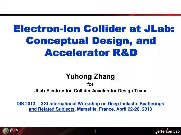
Electron-Ion Collider at JLab : Conceptual Design, and Accelerator R&D. Yuhong Zhang for JLab Electron-Ion Collider Accelerator Design Team DIS 2013 -- XXI International Workshop on Deep Inelastic Scatterings and Related Subjects , Marseille, France, April 22-28, 2013. Outline.

E N D
Electron-Ion Collider at JLab: Conceptual Design, and Accelerator R&D Yuhong Zhang for JLab Electron-Ion Collider Accelerator Design Team DIS 2013 -- XXI International Workshop on Deep Inelastic Scatterings and Related Subjects, Marseille, France, April 22-28, 2013
Outline • Introduction • Machine Design Baseline • Anticipated Performance • Accelerator R&D Highlights • Summary
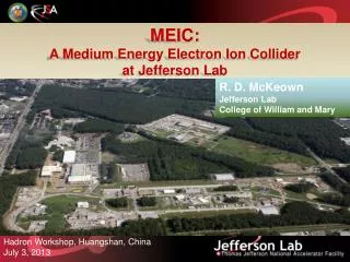
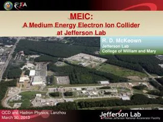
Y. Zhang, IMP Seminar Introduction • A Medium energy Electron-Ion Collider (MEIC) at JLab will open new frontiers in nuclear science. • The timing of MEIC construction can be tailored to match available DOE-ONP funding while the 12 GeV physics program continues. • MEIC parameters are chosen to optimize science, technology development, and project cost. • We maintain a well defined path for future upgrade to higher energies and luminosities. • A conceptual machine design has been completed recently, providing a base for performance evaluation, cost estimation, and technical risk assessment. • A design report was released on August, 2012.
MEIC Design Goals Base EIC Requirements per INT Report & White Paper Energy(bridging the gap of 12 GeV CEBAF & HERA/LHeC) Full coverage of s from a few 100 to a few 1000 GeV2 Electrons 3-12 GeV, protons 20-100 GeV, ions 12-40 GeV/u Ion species Polarized light ions: p, d, 3He, and possibly Li, and polarized heavier ions Un-polarized light to heavy ions up to A above 200 (Au, Pb) Up to 2 detectors Luminosity Greater than 1034 cm-2s-1 per interaction point Maximum luminosity should optimally be around √s=45 GeV Polarization At IP: longitudinal for both beams, transverse for ions only All polarizations >70% desirable Upgradeable to higher energies and luminosity 20 GeV electron, 250 GeV proton, and 100 GeV/u ion Y. Zhang, IMP Seminar
MEIC/EIC Layout MEIC (Stage-I EIC) Ion linac IP CEBAF IP Pre-booster Full Energy (Stage-II EIC)
MEIC Layout Medium-energy IPs with horizontal beam crossing 12 GeV CEBAF • Interaction point locations: • Downstream ends of the electron straight sections to reduce synchrotron radiation background • Upstream ends of the ion straight sections to reduce residual gas scattering background • Vertical stacking of nearly identical rings (max. deviation: 4 m; ring circumferences: 1350 m) • Ion beams execute vertical excursion to the plane of the electron orbit for a horizontal crossing • Horizontal crab crossing (50 mrad) at Ips; Figure-8 crossing angle: 60 deg. Ion path Interaction Regions Electron path Large Ion Booster Ion Collider Electron Collider
Y. Zhang, IMP Seminar New Ion Complex • Goals: covering all required ion species & energies, matching phase-space structures • Challenges: beam formation space charge effect at low energy • maintaining beam phase density intra-beam scatterings • Low energy DC electron cooling for assisting accumulation of heavy ions • SRF linac and boosters. No transition energy crossing in all rings. • High energy electron cooling Large booster collider ring ion sources SRF Linac pre-booster Low Energy DC electron cooling ERL electron cooling * Numbers in parentheses represent energies per nucleon for heavy ions
MEIC Design Point Parameters Slide 8
MEIC Design Report • JSA Science Council 08//29/12) • “… was impressed by the outstanding quality of the present MEIC design” • “The report is an excellent integrated discussion of all aspects of the MEIC concept.” • Overall MEIC design features: • High luminosity over broad range • Highly polarized beams (including D) • Full acceptance & high luminosity • Minimized technical risk and R&D arXiv:1209.0757 Design concept is stable EPJA article by JLab theory on MEIC science case (arXiv:1110.1031; EPJ A48 (2012) 92)
Y. Zhang, IMP Seminar Performance: High Luminosity e-P collision • High luminosity over a broad energy range • MEIC peak luminosity above 1034 cm-2s-1 • (A full/high detector acceptance can be achieved simultaneously) e-A collision A. Accardi
Y. Zhang, IMP Seminar MEIC High Luminosity Concept • MEIC design concept for high luminosity is based on high bunch repetition rate CW colliding beams KEK-B has reached>2x1034/cm2/s • JLab is poised to replicate same success in an electron-ion collider: • A high repetition rate electron beam from CEBAF • A new ion complex specifically designed to match e-beam • Multi-phase electron cooling of ion beams • Beam Design • High repetition rate • Low bunch charge • Very short bunch • Very small emittance • IR Design • Small β* • Crab crossing • Cooling • Multi-phase • During collision Slide 11
Performance: High Ion Polarization We are quite confident MEIC could deliver superior ion polarization! Primary technology innovation: Figure-8 ring All ion rings (two boosters, a collider) have a figure-8 shape Most simple (in principle) • Spin precession in the left &right parts of the ring are exactly cancelled • Special insertions invented to provide energy independent spin tune off 0 at constant orbit • Ensures an easy means of spin preservation and manipulation • Avoids energy-dependent spin sensitivity for ion all species Polarized deuterons • The only practical way to accommodate medium energy polarized deuterons which allows for “clean” neutron measurements No-pain operation Offersfirm no-pain long term operation runs for all polarized beams at all energies, • Intrinsic spin resonances stay away • High order intrinsic effects are diminished with cooled emittance Slide 12
Y. Zhang, IMP Seminar Performance: High Electron Polarization • Universal Spin Rotator • rotating spin from vertical to longitudinaldirection • energy independent • orbit (geometry) independent • MEIC Physics program demands • High polarization (>70%) and long life-time (>10 min.) • Longitudinal direction at IPs and spin flip • MEIC electron polarization design • CEBAF polarized electron source (superior, >85%) as a full energy injector • Beam in the ring can be frequently replaced • Inject e-beam with vertical spin in arcs • Using universal spin rotators for longitudinal spin at IP • Employing spin matching to minimizing depolarization spin arc dipole arc dipole Solenoid 1 Solenoid 2 spin e beam φ1 φ2 α1≈8.8º α2≈4.4º
Performance: Low Energy Electron-Ion Collisions Implementation of low energy electron-ion collisions • Converting large ion booster to a collider ring • Peak luminosity can reach 1033 cm-2s-1 • Could be a 3rd IP as an additional capability or the 1st phase of EIC@JLab • Design flexibility, detector interchangeable • No SC ring for large booster easier to start • Low technology R&D challenges, reduce risk Low energy ion ring (large booster)10 to 25 GeV IP Electron ring 3 to 12 GeV
Performance: Polarized Positrons MEIC/LEIC can collide polarized positrons with ions, achieving high luminosity similarly to electron-ion collisions Only be possible with a ring-ring collider (a lepton storage ring) • Use CEBAF beam to generate unpolarized positrons (Development of an optimum scheme in process) • Accelerate in CEBAF, inject and stack in the lepton storage ring • Arrange and wait for possibly fastest self-polarization (Sokolov-Ternov effect) (at 10-12 GeV, and/or by using special wigglers) • Ramp energy down to the target value for experiment • Use spin-resonance SC cavities for spin flip (frequent flipfor the whole beam or one-time flip for half beam)
Y. Zhang, IMP Seminar MEIC Accelerator R&D Toward CD1 • Electron cooling • Electron cooling of medium energy ion beam (by simulations) • ERL circulator cooler design optimization, technology development • Cooling with bunched electron beams • ERL-circulator cooler demo (using JLab FEL facility) • Interaction region • Optimization of detector integration • Sufficient dynamic aperture with low beta insertions • Beam Synchronization • A scheme has been developed; SRF cavity frequency tunability study is in progress • Polarization • Demonstrate superior ion polarization with figure-8 ring • Electron spin matching • Collective beam effects • (Long time scale) beam-beam with crab crossing • Space charge effects in pre-booster • Electron cloud in the ion rings and mitigation • Ion Injector complex optimization and beam studies Bold font indicates priority
Y. Zhang, IMP Seminar Cooling: No. 1 R&D Priority • Essential to achieve high luminosity for MEIC • Based on traditional electron cooling • Multi-phase cooling scheme Pre-booster:Coolingfor assisting accumulation of positive ion beams (Using a low energy DC electron beam, existing technology) Collider ring: Initial cooling after injection Final coolingafter boost & re-bunching, reaching design values Continuous coolingduring collision for suppressing IBS (Using new technologies) Bunched e-beam Medium energy Circulator ring ERL • Cooling of medium energy (up to 100 GeV) hadrons w/ a bunched electron beam (state-of-art: 8 GeV p-bar at Fermilab, DC) • Generating 3 A, 55 MeV cooling electron beam
Design Concept: ERL Circulator Cooler solenoid • Design Choices • Energy Recovery Linac (ERL) • Compact circulator ring • to meet design challenges • Large RF power (up to 81 MW) • Long gun lifetime (average 1.5 A) • Required technologies • High bunch charge magnetized gun • High curr. ERL (55 MeV, 15 to150 mA) • Ultra fast kicker ion bunch recirculation/decompression electron bunch Cooling section dump CCR dechirper energy recovery beam exchange system cooling solenoids Fast kicker Fast kicker circulator ring ERL rechirper e-bunches circulates 10+ turns reduction of current from an ERL by a same factor injector recovery/recompression dump injector SRF Linac Optimization: Put it at center of the Figure-8 ring, for eliminating the long return path doubles the cooling rate 18 Slide 18
Design Concept Optimization • The “ready-to-build” version utilizes only (loosely speaking) the existing and proven accelerator technologies. • “Weak” ERL cooling means using much lower electron current
Existing Cooling Technologies ion bunch solenoid • “Weak” ERL Cooler • No circulating ring (no fast kicker) • Electron current: ~100 mA (state-of-art) • Needs ERL (e-beam power: 5.5 MW) • Bunched Stochastic Cooling electron bunch Cooling section RHIC Fast kicker circulator ring Fast kicker Medium energy Bunched e-beam ERL Circulator ring • Only for heavy ions • Bandwidth: 4~9 GHz • Lead ions: 5.1x10⁷ per bunch • Cooling time: ~ 14 min dump injector SRF Linac
MEIC Phased Cooling Scheme Loosely speaking, based on existing technologies 5.6~14 Add “weak” ERL cooling &stochastic cooling (heavy ions) during collision Full capacity electron cooling (ERL-circulator cooler) Luminosity (1033 1/cm2/s) ~3.3 Low energy DC cooling only at pre-booster injection ~1.1 Add DC cooling at top energy (3 GeV) of pre-booster ~0.41
Cooling Experiments at IMP Institute of Modern Physics, Chinese Academy of Science Two storage rings with DC coolers for heavy ion coasting beams Purpose: testing cooling with a bunched electron beam (AndrewHutton) Modulated the DC beam into a bunched beam with a high repetition rate by applying a pulsed voltage to the bias-electrode of the electron gun (Hongwei Chao, IMP) Replacing the existing thermionic gun by a JLab photo-cathode gun (Matt Poelker, JLab) Low cost, non-invasive experiment, as early as 08/2013 Supporting the “Ready-to-Build” design concept Phase II: adding an RF cavity for bunching the ion beams) testing a bunched electron beam to cool a bunched ion beam DC cooler Medium energy Bunched e-beam ERL Circulator ring
ERL-Circulator Cooler Proof-of-Concept Experiment at JLab FEL-ERL Purpose • Demonstrate the design concept • Develop/test key accelerator technologies (faster beam kickers, etc.) • Study dynamics of the cooling electron bunches in a circulator ring Phase 1 scope • Using the existing ERL without new upgrade except two 180° beam lines (available at JLab) • Supporting MEIC to deliver the high luminosity (5.6~14 x 1033 1/cm2/s), not needed for the “ready-to-build” version • To be completed (hopefully) before 2016 Dechirper Rechirper Cooler Test Facility @ JLab FEL ERL Medium energy Bunched e-beam ERL Circulator ring
Y. Zhang, IMP Seminar Summary • The MEIC design has been completed and a comprehensive design report has been released. • Low energy electron-ion collisions can be realized either as an add-on or as a first stage, expanding the science reach • We anticipate superior performance of MEIC, particularly in luminosity, lepton and light ion polarization, detection acceptance, etc. • The focus of the MEIC team has shifted to design optimization (low cost and less technical uncertainty) and critical accelerator R&D. • Cooling is considered the most critical R&D • Optimizing the cooling scheme by using more existing (DC) technology • “Ready-to-Build” enables luminosity above 1033 cm-2s-1, meets the EIC white paper requirement; • R&D will bring an order of magnitude booster • Two low-cost experiments will demonstrate the design concept
Acknowledgement S. Abeyratne, A. Accardi, S. Ahmed, D. Barber, J. Bisognano, A. Bogacz, A. Castilla, P. Chevtsov, S. Corneliussen, W. Deconinck, P. Degtiarenko, J. Delayen, Ya. Derbenev, S. DeSilva, D. Douglas, V. Dudnikov, R. Ent, B. Erdelyi, P. Evtushenko, Yu. Filatov, D. Gaskell, R. Geng, V. Guzey, T. Horn, A. Hutton, C. Hyde, R. Johnson, Y. Kim, F. Klein, A. Kondratenko, M. Kondratenko, G. Krafft, R. Li, F. Lin, S. Manikonda, F. Marhauser, R. McKeown, V. Morozov, P. Nadel-Turonski, E. Nissen, P. Ostroumov, M. Pivi, F. Pilat, M. Poelker, A. Prokudin, J. Qiang, R. Rimmer, T. Satogata, H. Sayed, M. Spata, M. Sullivan, C. Tennant, B. Terzić, M. Tiefenback, H. Wang, S. Wang, C. Weiss, B. Yunn, Y. Zhang 11 Moscow Institute of Physics & Technology 12 MuonsInc. 13 Northern Illinois University 14 Old Dominion University 15 Paul Scherrer Institute 16 SLAC National Accelerator Lab 17 Science and Technique Lab Russia 18 Universidad de Guanajuato 19 University of Wisconsin-Madison 1 Jefferson Lab 2 Argonne National Laboratory 3 Brookhaven National Laboratory 4 Catholic University of America 5 College of William and Mary 6 DESY 7 Hampton University 8 Idaho State University 9 Joint Institute for Nuclear Research, Dubna 10 Lawrence Berkeley National Laboratory