Download
1 / 54
540 likes | 696 Views
CLIC Main Beam Generation Complex. Louis Rinolfi. for the CLIC Injector collaboration. General CLIC layout for 3 TeV. Drive Beam Generation. Main Beam Generation. CLIC Main Beam parameters. At the entrance of the Main Linac for e - and e +. CLIC Main Beam generation.

E N D
CLIC Main Beam Generation Complex Louis Rinolfi for the CLIC Injector collaboration
General CLIC layout for 3 TeV Drive Beam Generation Main Beam Generation
CLIC Main Beam parameters At the entrance of the Main Linac for e- and e+
CLIC Main Beam generation CLIC Main Beams generation: 4 studies are ongoing to produce e+/e- with the requested parameters at the entrance of the Pre-Damping Ring (PDR): 1) Baseline configuration: 3 TeV (c.m.) - polarized electrons (5x10⁹ e-/bunch) and unpolarized positrons (7.6x10⁹ e+/bunch). Pulse of 156 ns long with 312 bunches 2) Double charge configuration: 500 GeV (c.m.) - polarized electrons (10x109 e-/bunch) and unpolarized positrons (15.2x10⁹ e+/bunch) with same pulse length as above 3) Polarized positron configuration: 3 TeV (c.m.) - polarized e- and e+ with same parameters as for the baseline 4) Low energy configuration (< 3 TeV): 4.1) Polarized e- and unpolarized e+ with the highest repetition frequency 4.2) Polarized e- and unpolarized e+ with half the baseline charge but 800 bunches
CLIC Main Beam Injector Complex IP e- Main Linac e+ Main Linac e- BC2 e+ BC2 12 GHz 12 GHz 12 GHz, 100 MV/m, 21 km 12 GHz, 100 MV/m, 21 km 9 GeV 48 km IP = Interaction Point SR= Spin Rotator BC = Bunch Compressor DR= Damping Ring PDR= Pre-Damping Ring AMD= Adiabatic Matching Device 3 TeV Base line configuration 2009 Booster Linac 6.14 GeV 4 GHz SR e+ BC1 4 GHz e- BC1 4 GHz 2.86 GeV 2.86 GeV e- DR e+ DR polarized e- unpolarized e+ e- PDR e+ PDR 2.86 GeV 2.86 GeV SR Injector Linac 2.66 GeV 2 GHz e-/g Target g/e+ Target Laser Pre-injector e+ Linac 200 MeV Pre-injector e- Linac 200 MeV Thermionic e- gun Primary e- Beam Linac 5 GeV DC gun Polarized e- 2 GHz AMD 2 GHz 2 GHz
CLIC Main Beam Injector Complex IP e- Main Linac e+ Main Linac e- BC2 e+ BC2 12 GHz 12 GHz 12 GHz, 100 MV/m, 21 km 12 GHz, 100 MV/m, 21 km 9 GeV 48 km 3 TeV Compton based configuration Booster Linac 6.14 GeV 4 GHz e+ BC1 4 GHz e- BC1 4 GHz 2.86 GeV 2.86 GeV e- DR e+ DR polarized e+ polarized e- e- PDR e+ PDR 2.86 GeV 2.86 GeV Spin rotator Spin rotator RF gun Drive e- Beam Linac 1 GeV Injector Linac 2.66 GeV 2 GHz Compton ring 2 GHz g/e+ Target Laser Pre-injector Linac for e+ 200 MeV g Pre-injector Linac for e- 200 MeV YAG Laser DC gun Polarized e- Stacking cavity 2 GHz 2 GHz AMD
CLIC Main Beam Injector Complex IP e- Main Linac e+ Main Linac e- BC2 e+ BC2 3.5 km 12 GHz 12 GHz 12 GHz, 100 MV/m, 21 km 9 GeV 48 km 3 TeV Undulator based configuration Booster Linac 6.14 GeV 4 GHz e+ BC1 4 GHz e- BC1 4 GHz 2.86 GeV 2.86 GeV e- DR e+ DR polarized e- polarized e+ e- PDR e+ PDR 2.86 GeV 2.86 GeV Spin rotator Spin rotator Injector Linac 2.66 GeV 2 GHz Auxiliary source e-/e+ Target Laser Pre-injector e+ Linac 200 MeV Pre-injector e- Linac 200 MeV Primary e- Beam Linac 200 MeV Thermionic e- gun DC gun Polarized e- 2 GHz 2 GHz AMD 2 GHz
CLIC e- beam time structure for 3 TeV 20 ms Repetition Rate (50 Hz) 156 ns, 312 micro-bunches 0.5 ns 1.999 GHz (I/I) bunch to bunch ≤ 1% (I/I) pulse to pulse ≤ 0.2 %
DC gun high voltage: why to increase? Reduce space-charge-induced emittance growth Maintain smaller transverse beam dimensions and short bunch length Other possible positive impacts which remains to be demonstrated: Surface charge limit issues are reduced Longer life time But the big issue: Field emission => HV breakdown => photocathode damages => destruction Currently DC gun: Vgun 100 kV and Ggun 5 MV/m
Photocathodes Superlattice GaAs: Layers of GaAs on GaAsP 100 nm 14 pairs No strain relaxation QE ~ 1% Pol ~ 85% @ 780 nm First successful superlattice by KEK/Nagoya group. T. Omori et al, Phys Rev Lett 67 (1991) pp3294-3297. Large band-gap photocathode gave a high current. First GaAs-GaAsP photocathode with superlattice structure, strain, modulation doping by KEK/Nagoya group. T. Nakanishi at al, NIM, A455, pp.109-112 (2000) Developments at SLAC. “Systematic study of polarized electron emission from strained GaAs/GaAssuperlatticephotocathodes” T. Maruyama et al., Applied Physics Letter, Vol 85, N 13, 2004 Developments at JLAB. “Lifetime Measurements of High Polarization Strained Superlattice Gallium Arsenide at Beam Current > 1 mA Using a New 100 kV Load Lock Photogun”, J. Grames et al., Particle Accelerator Conference, Albuquerque, NM, June 25-29, 2007
Pulsed laser parameters for e- source • ≈ 775 - 780 nm (Laser wavelength) QE ≈ 0.2 % ≈ 90%
cw laser parameters for e- source • ≈ 775 - 780 nm for GaAs photocathodes QE ≈ 0.7 % (SLAC experiment) ≈ 70% for the bunching system
Polarized e- produced at SLAC J. Sheppard / SLAC @CLIC09 workshop The total charge produced is a: factor 3 above the CLIC requirement for 0.5 TeV factor 5 above the CLIC requirements for 3 TeV QE ~ 0.7 % CLIC Goal (0.5 TeV) The measured polarization is ~ 82 % CLIC Goal (3 TeV)
Challenges for the e- source Gun: Reliable load locked gun High voltage 100 kV - 350 kV => No field emission Ultra-high vacuum requirments => range of 10-12 Torr Cathode/anode optics => challenge for uniform focusing properties Photocathode: Production of the full current with space charge and surface charge limits High polarization: 80 % - 90% => Measurements and accuracy High Quantum Efficiency: 0.5 – 1 % => Photo-cathodes preparation techniques Long life time Laser: Laser frequency: 2 GHz or cw Pulse length: 0.1 to 800 ns Pulse energy: > 1 mJ
DC guns at SLAC and JLAB SLAC Jlab
Bunching system simulations F. Zhou / SLAC
Pre-Injector e- Linac MKL 03 MKL 02 MKL 01 50 Hz 50 Hz 50 Hz 40 MW 40 MW 40 MW 2 GHz 2 GHz 2 GHz SLED SLED DC Gun A1 A2 A3 A4 B1 PB2 PB1 200 MeV 20 MeV • Accelerating cavities: • Number of cavities: N = 4 • Length: L = 3 m • Aperture radius: r = 20 mm • Energy Gain: DE = 45 MeV • Accelerat. gradient: Ez = 15 MV/m • Frequency: f = 2 GHz
Comparison with SLC X 20 X 66
Primary Electron Beam Linac g/e+ Target e-/g Target Primary electron beam Linac Thermionic e- gun Bunching system 5 GeV 2 GHz Crystal Amorphous Electron beam parameters on the crystal target With a yield of 0.9 e+/e- at 200 MeV and 7.6x10⁹ e+/bunch needed at the entrance of the Pre-Damping Ring, the requested charge is 10 x109 e-/bunch on the target. It is a classical linac but the design of the source, the bunching system and the linac itself remains to be done.
FLUKA simulations for a W target E. Eroglu / Uludag University Excellent agreement between EGS4 and FLUKA Energy deposition from FLUKA code MeV / e- Amorphous W target (CLIC Note 465): Electron beam energy: 2 GeV Charge: 2x10¹² e-/pulse Repetition frequency: 200 Hz
Unpolarized e+ source Dipole R. Chehab & A. Variola / LAL e- e- e- Primary electron beam Linac e+ g 5 GeV amorphous e+ crystal Crystal thickness: 1.4 mm Oriented along the <111> axis Distance (crystal-amorphous): 3 m Amorphous thickness: 10 mm
Channeling process < 2U/E U = potential (on axis) q = normal incidence angle for channeling E ~ 0.7 GeV threshold for channeling inside W Higher E, higher channeling effects crystal amorphous T. Suwada / KEK
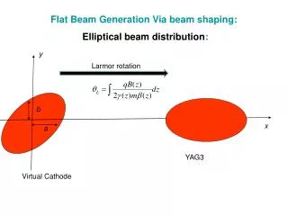
Adiabatic Matching Device (AMD) • The characteristic features of its acceptance are: • Geometrical acceptance: • (R0)max = a.[Bs/Bo]1/2 • Transverse momentum • (pT)max = e[BoBs]1/2a B(z) (Gauss) B(z)= Bo/(1+az) a = 22 m-1 a = aperture radius = 20 mm B0 = 6 T Bs = 0.5 T 20 cm < L < 50 cm Bs Z (cm) The AMD transforms the initial emittance with large angles and small dimensions into an emittance with small angles and large dimensions => easier to transport
Positron beam distributions O. Dadoun / LAL Positron distribution at the amorphous target exit for 2 different primary electron beam energy Most of e+ are below 100 MeV 10 GeV 3 GeV The field law: B (z) = Bo/(1+az) is introduced in GEANT4 and the accepted e+ yield is calculatedat the AMD exit Transverse emittances Blue = upstream AMD Red = downstream AMD
Flux concentrator T. Kamitani / KEK Development BINP and KEK
Layout of e+ targets at KEKB T. Takahashi / Hiroshima University Hybrid targets are installed on the KEKB Linac 1.9 Preliminary tests results: enhancement of factor ~ 2 for the e+ yield when the crystal is aligned and not aligned e+ yield
e+ source for CLIC 500 GeV => very close to the breakdown limit => Double target station ? => Double beam diagnostics Double charge / bunch => Double Peak Energy Deposition Density inside the target g/e+ Target e-/g Target Pre-injector e+ Linac 200 MeV 2 GHz AMD Primary beam Linac for e- Thermionic e- gun To injector linac RF deflectors 5 GeV 2 GHz e-/g Target g/e+ Target Pre-injector e+ Linac 200 MeV 2 GHz AMD
Pre-Injector e+ Linac Adiabatic Matching Device Bunch compressor Amorphous Target Pre-injector linac Dipoles Crystal To the Injector Linac e- e- g g e+ Dipole e+ 200 MeV Yield = 0.9 e+ / e- Solenoid Cavities 2 GHz • AMD • Length : L = 20 cm • Magnetic Filed: B = 6 - 0.5 T • Final Aperture: r = 2 cm • Accelerating cavities: • Number of cavities: N = 4 • Length: L = 3 m • Aperture radius: r = 20 mm • Energy Gain: DE = 50 MeV • Maximum Gradient: Ez (r=0) = 17 MV/m • Frequency: f = 2 GHz • SOLENOID • Length : L = 41 m • Magnetic Filed: B = 0.5 T
Challenges for the e+ source A single hybrid targets station or several stations to cover all the CLIC needs Targets issues (Heat load dynamics, beam energy deposition, shock waves, breakdown limits, activation, ….) Adiabatic Matching Device (AMD) Capture sections (Transport and collimation of large emittances, high beam loading, 2 GHz unusual) Efficient use of existing codes (EGS4, FLUKA, Geant4, PPS-Sim, PSCSim, Parmela, ASTRA,…) Integration issues for the target station (remote handling in radioactive area) Radioactivity issues For polarized positron (=>Design and implementation of the spin rotators; => Polarization issues to analyze systematic errors of measurements) For the Compton schemes (=> Optical cavities at IP, powerful laser systems,…) For the Undulator scheme (=> Helical undulator, collimators, dumps, civil engineering for the tunnel,…) ……..
Injector Linac F0DO lattice at the beginning L0 L0 L0 L0 L0 L0 Matching from FODO to Triplet Q1 Q2 Q3 Q5 Q4 Q6 Q7 Triplet for the end of the linac Q6 Q5
Simulation results Injector Linac A. Vivoli / CERN Black distribution = end of Injector Linac Red distribution = captured inside the PDR To be optimized… e+ in PDR: 2747; Yield e+/e- =0.458
CLIC Pre-Damping Ring acceptance F. Antoniou Pre-Damping Ring design is based on these values PDR geometrical acceptance: H = V = 6 s
Layout of the Bunch Compressors F. Stulle / CERN BC1 BC2
Yield and charge of e+ beam Based on the lastest simulations, the yield and the charge have been revised along the Main Beam Injector Complex,
Charges along the Injector Complex IP e- Main Linac e+ Main Linac e- BC2 e+ BC2 12 GHz, 100 MV/m, 21 km 12 GHz, 100 MV/m, 21 km 3.7x10⁹ 4x10⁹ 4x10⁹ 3 TeV Base line configuration Booster Linac 6.14 GeV 4.1x10⁹ 4.1x10⁹ e+ BC1 e- BC1 4.2x10⁹ 4.2x10⁹ e- DR e+ DR Spin rotator 4.4x10⁹ 4.4x10⁹ e- PDR e+ PDR 4.6x10⁹ 4.6x10⁹ 7.6x10⁹ 5x10⁹ Injector Linac 2.66 GeV 9.8x10⁹ 20x109 5.5x10⁹ 10x109 6x10⁹ 5 GeV 200 MeV 200 MeV DC gun Polarized e- e-/g Target Pre-injector e+ Linac Pre-injector e- Linac Primary e- Beam Linac g/e+ Target AMD Thermionic e- gun Laser
CLIC Compton Ring E. Bulyak / NSC KIPT Energy spread Time (cw) Number of e- = 312 x 6.2 x 109 = 1.93 x10¹² in the ring I = 2 A Photon yield = 0.063 photons / e- / turn (simulation) Photon flux: 1.33x10¹⁶ photons / s
CLIC based Compton Ring Compton Ring: E = 1.06 GeV C = 46.8 m VRF = 200 MV fRF = 2 GHz CP = 0.05 m 1100 turns makes 312 bunches with 4.4x10⁹ e+/bunch e+ DR 2.86 GeV 2.86 GeV e+ PDR and Accumulator ring 156 ns/turn, 312 bunches with 6.2x10⁹ e-/bunch RF gun Injector Linac 2.66 GeV Drive Linac 1 GeV 2 GHz Compton ring 2 GHz Laser pulse: E = 1.164 eV r = 0.005 mm l = 0.9 mm Pre-injector Linac for e+ 200 MeV g/e+ Target g 156 ns x1100 turns => 170 ms pulse length for both linacs 4x10⁸ photons /turn/bunch Stacking cavity 2 GHz YAG Laser 4x10⁶ pol. e+/turn/bunch
CLIC Compton ERL T. Omori / KEK N of stack (same bucket) = 2003 CLIC requires 4.4 x 10⁹ e+/ bunch 50 Hz Linac (if necessary) 4.4x10⁹ e+/bunch 4.2x10⁹ e+/bunch
CLIC Compton Linac g to e+ conv. target 60MeV g beam 6GeV e- beam 30MeV e+ beam ~2 m ~5 ns 312 pulses V. Yakimenko / BNL Ng / Ne- = 1 (demonstrated at BNL) Ne+ / Ng = 0.02 (expected) i.e. 50 gammas to generate 1 e+ Data for CLIC: Ne+ = 6.4 x 10⁹ / bunch ~ 1 nC Ne- = 0.32 x 10¹² / bunch ~ 50 nC With 5 nC / e- bunch and 10 Compton IP's => 1 nC / e+ bunch
CLIC Undulator scheme W. Gai / ANL Ti alloy Cleaning chicane e+ 250 GeV 450 m
CLIC Undulator scheme L. Zang / CI Undulator 100 m long with: K = 0.92 lu = 12 mm
Spin Rotators Requirements: 1) Rotate spin to the vertical plane before pre-damping ring so polarization is not destroyed during damping. 2) Rotate spin after the last turnaround to have the desired polarization at the e+e- IP, e.g. longitudinal polarization at IP. May be can be done upstream the Booster Linac. for ILC Spin rotation is done with a combination of spin rotation solenoids and spin precession in dipole bends K. Moffeit / SLAC is be rotated 90o in a solenoid field
RF frequency from 2 GHz down to 1 GHz ? Impact of lowering the RF frequency in the low energy part of the injector F. Antoniou, M. Barnes, A. Grudiev, L. Rinolfi, G. Rumolo, Y. Papaphilippou, F. Stulle, A. Vivoli November 18th, 2009