Download
1 / 15
210 likes | 452 Views
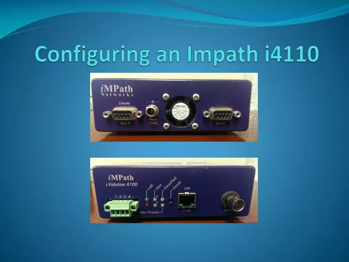
Configuring an Impath i4110. Configure the IP Address. Connect to encoder’s serial port Power on encoder Connect serial cable to “Data A” Hold in “Console” until “Data A” light turns solid red. Open Putty with the proper settings (COM port may vary) Click Open

E N D
Configure the IP Address • Connect to encoder’s serial port • Power on encoder • Connect serial cable to “Data A” • Hold in “Console” until “Data A” light turns solid red
Open Putty with the proper settings (COM port may vary) • Click Open • Type in the user name and password • impath • impath
1. Type “maint” and hit enter 2. Select “3” and hit enter 3. Select “3” and hit enter 4. Configure options 1, 2, 3 like below
5. “Q” out of the menus saving if asked • 6. Type “reboot” and hit enter • At this point you can disconnect your serial cable
Configuring the Terminal Server Connect the encoder to the network or directly to you laptop with a cat5 cable Connect to the encoder with putty, this time using the “Telnet” connection type Enter the username and password
Enter the “maintenance” menu Select “4” to open service manager menu Select “2” to configure serial port options
#1 “Data Port Interface Settings” comes pre-configured to work with our Vicon cameras and in most cases will not need to be configured. #2 “Data Circuit Network Settings” is where we will configure the Terminal Server Mode and port number.
Select “2” and then select the port you wish to configure 1 is for port A 2 is for port B By default both ports are disabled. We typically use port B for the camera so that we don’t have unplug the camera if we want to access the encoder with a serial cable which can only be done on port A Select “2” to configure port B (unless the port is damaged and you are switching to port A)
Select “1” to change the Network Service Mode Select “2” to configure the terminal server to “Unicast TCP Server” mode
Select “2” to change the TCP port to “4002” “Q” out of the menus typing “y” to save when asked until you get back to the first menu
1. Select “4” 2. Select “1” 3. Select “3” 4. Select “1”
Option 1 “Video Encoder” should be left at the factory defaults
Option 2 “Video Network” is where we set the multicast address/port and stream type Configure options 1, 2, 4, and 8 as seen here “Q” out of the menus typing “Y” to save when asked until you reach the “maint” menu The encoder is now ready to be deployed in the field