Download
1 / 34
340 likes | 452 Views
PUMPS, VALVES, & FANS. …Moving fluids. Objectives. Comprehend the basic construction and application of valves used Comprehend the basic operation and application of different pumps Know Bernoulli’s principle, the concept of pressure, & Net Positive Suction Head

E N D
PUMPS, VALVES, & FANS …Moving fluids
Objectives • Comprehend the basic construction and application of valves used • Comprehend the basic operation and application of different pumps • Know Bernoulli’s principle, the concept of pressure, & Net Positive Suction Head • Be familiar with operation and application of centrifugal & axial fans
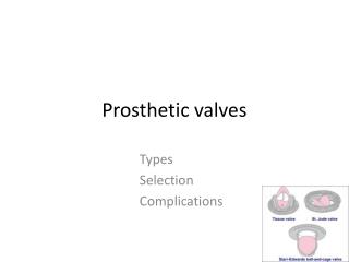
Valves • Def’n: devices which control the amount and direction of fluid flow in piping systems • Typically made of bronze, brass, iron, or steel alloy • Components: - Valve body - Packing - Disc - Packing gland/nut - Seat - Stem - Bonnet - Wheel
Types of Valves • Two basic groups: • Stop valves - used to shut off or partially shut off the flow of fluid ( ex: globe, gate, plug, needle, butterfly) • Check Valves - used to permit flow in only one direction (ex: ball-check, swing-check, lift-check) • Special types: • Relief valves • Pressure-reducing valves • Remote-operated valves
Stop Valves • Globe Valves • Most common type of stop valve • Used in steam, air, water, & oil lines • Disc attached to valve stem rests against seat to shut off flow of fluid • Adv: Used for throttling • Disadv: flow resistance
Stop Valves • Gate Valves • Used when there must be straight-line flow of fluid w/ min. resistance • Gate usually wedge-shaped or a vertical disc • Adv: No flow restrictions • Disadv: poor throttling
Stop Valves • Butterfly Valves • Used in water, fuel, and ventilation systems • Adv: small, light-weight, & quick-acting • Disadv: leaks early & only low-flow throttle • Ball Valves • Similar to butterfly valves • Normally found in seawater, sanitary, trim and drain, and hydraulic systems
Check Valves • Controls direction of flow • Operated by flow of fluid in pipe • Types: • Swing check - disc moves through an arc • Lift check - disc moves up and down • Ball check - ball is located at end of stem and lifts to allow flow
Relief Valves • Used to protect piping system from excessive pressure • Opens automatically when fluid pressure becomes too high (pressure acts against spring pressure) • Relieving pressure set by an adjusting screw
Pressure-reducing Valves • Used to automatically provide a steady, lower pressure to a system from a higher pressure source • Used in air, lube-oil, seawater, and other systems
Remote-operated Valves • Valves that allow operation from distant stations • Types: • Mechanical - uses reach rods and gears • Hydraulic - uses fluid and piston set up • Motor - uses and electric or pneumatic motor • Solenoid - uses coil and core mechanism to open or close on an electric signal
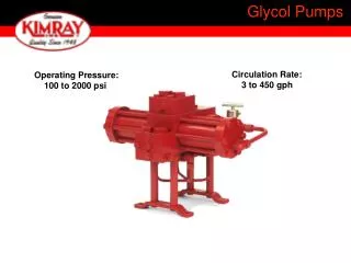
Pumps • Def’n: device that uses and external power source to apply force to a fluid in order to move it from one place to another • Must overcome: • (1) frictional forces from large quantities of fluid • (2) difference in static pressure between two locations • Must provide any velocity desired
Pumps – Bernoulli’s Theorem • Pressure head: measure of fluid’s mech. PE • Velocity head: measure of fluid’s mech. KE • Friction head: measure of energy lost that heats fluid Z1 + P1/r + V12/2g = Z2 + P2/r + V22/2g + [(U2 – U1) – W – Q] q + wshaft = (h2 – h1) + (v22 – v12)/2 + g(z2 –z1) Z/z: fluid height; P: fluid pressure; r: fluid density V/v: fluid velocity U: internal energy W/w: work Q/q: heat transferred h: enthalpy g: grav. acceleration • BOTTOM LINE: Total energy within the control volume is constant under SS conditions.
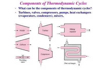
Components of Pumps • Drive mechanism (steam, electric, gear) • Pump shaft • Impeller or piston • Casing
Types of Pumps • Positive Displacement • Fixed volume of fluid is displaced during each cycle regardless of static head/pressure pumping against • Uses either a piston, gear, or screw type (reciprocating, rotary gear, rotary screw, etc)
Pumps • Non-positive Displacement: volume of fluid is dependent on static head/pressure • Centrifugal: impeller inside a case (called volute). Impeller is a disc w/ curved vanes mounted radially (like a paddle wheel) • Suction is the Eye -> fluid accelerated as it travels outward & then enters volute • Propeller: uses prop inside casing to move fluid -> not used much in Navy
Pumps • Jet pumps: • Bernoulli’s principle and no moving parts • Velocity Head vs. Pressure head hin + vin2/2 = hout + vout2/2
Jet Pump • Types: • Eductor - used to pump liquids • Ejector - used to pump gases
Pump Characteristic Curves • Pump Parameters: • N = pump speed, RPM • V = volumetric flow rate, GPM • Hp = pump head (discharge pressure), psig • P = power required, Hp • Centrifugal Pump Laws • V a N • Hpa N2 • W a N3
Positive Displacement Pumps N1 N2 N2 = ____ Hp GPM
Centrifugal Pumps • Parallel Pumps V2 = ____ Hp2 = ____ Hp 2 Pumps 1 Pump GPM
Centrifugal Pumps • Series pumps (called staging) V2 = ____ Hp2 = ____ Hp 2 Pumps 1 Pump GPM
Net Positive Suction Head • Def’n: that pressure required at the suction of a pump to prevent cavitation • So what is cavitation? - the formation of bubbles due to low pressure area and the subsequent collapse upon migration to a high pressure area • Cavitation causes noise and damage
Net Positive Suction Head • Need enough pressure on the suction side so that the pump does not reduce pressure @ the eye to cause P < Psat • If P < Psat, water flashes to vapor causing damage to the pump • What are possible means of providing NPSH to prevent cavitation?
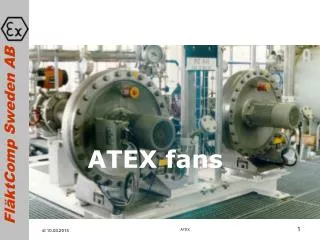
Fans • Same Principle as Non-positive displacement pumps • Types: • Centrifugal: majority used for compressors • Axial (like propeller): cooling fans
Questions? Questions?