Download
1 / 83
840 likes | 1.3k Views
Fluidic and Microfluidic Pumps, Micropumps, Compressors, Fans and Blowers an Overview. Craig E. Nelson - Consultant Engineer. Pumps, Fans, Compressors and Blowers Increase Fluid Energy. Velocity – Kinetic Energy a) Fans b) Propulsion Propellers

E N D
Fluidic and Microfluidic Pumps, Micropumps, Compressors, Fans and Blowers an Overview Craig E. Nelson - Consultant Engineer
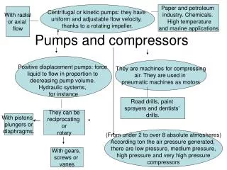
Pumps, Fans, Compressors and Blowers Increase Fluid Energy • Velocity – Kinetic Energy • a) Fans • b) Propulsion Propellers • Pressure – Internal Energy – Enthalpy - Heat • a) Pumps • b) Compressors • Velocity and Pressure – Some of Both • a) Pumps • Blowers
Fluidic System Pressure vs. Flow Curve Determines the type of Pump Needed
The Bernoulli equation is a special statement of the general energy equation Work added to the system is referred to as pump head (hP) Losses from the system are referred to as head loss (hL) Pressure (lbf/in2) is a form of work Strictly Mechanical Energy so we get the equation: P1 + PE1 + KE1 + WK = PE2 + KE2 + WKFRIC + P2 BERNOULLI’S THEOREM
Z1 + (P1/) + (V12/2g) = Z2 + (P2/) + (V22/2g) + hP - hL BERNOULLI’S Equation Z : Elevation (ft) P : Pressure (lb/ft2) : Density (lb/ft3) V : Velocity (ft/sec) g : acceleration (32.2 ft/sec2) Hp: pump head (ft) HL: Head Loss (ft) = f(L/D)(V2/2Zg) where f : friction factor L: Length D: Diameter
The vertical difference between 2 levels of liquid Use FT to measure the pressure exerted by a body of liquid in term of weight Head α Pressure α Energy Velocity Head The distance a liquid would have to fall for a given V Hv = V12/2g Friction Head Hl= f(L/D)(V2/2Zg) where f : friction factor L: Length D: Diameter THE CONCEPT OF “HEAD”
Pressure Head STATIC DISCHARGE HEAD NET STATIC HEAD STATIC SUCTION PRESSURE PUMP
Head required to impart velocity to a liquid Equivalent to the vertical distance through which the liquid would have to fall to acquire the same velocity Equal to V2 / 2g Velocity Head
The force or pressure required to overcome friction is obtained at the expense of the static pressure head Unlike velocity head, friction head cannot be “recovered” or reconverted to static pressure head Thermal energy is usually wasted, therefore resulting in a head loss from the system Friction Head
Apply to centrifugal (non-positive displacement) pumps only V N Hp N2 W N3 V = volumetric flow rate N = speed of rotation Hp = pump head W = power required (prime mover) More Pump “Laws” . . .
Centrifugal and Fan Pump Elements DRIVE TYPE (electric motor, steam drive, gear driven, etc…) IMPELLER PUMP SHAFT & Seal DISCHARGE CASING SUCTION
Examples of Small Commercially Available and “Academic Research” Pumps Fans and Blowers