Download
1 / 12
160 likes | 457 Views
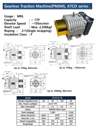
PMSM Loss Analysis. Liping Zheng 05/02/03. Winding Configuration. Litz-wire: 1.78 mm x 2.27 mm 50 strands @ AWG 30 Gap : 0.5 mm Stator Di: 25.5 mm Do: 38 mm Length: 25.4 mm Shaft diameter: 16 mm. Motor length: 80 mm Motor diameter: 40 mm. F. F.

E N D
PMSM Loss Analysis Liping Zheng 05/02/03
Winding Configuration Litz-wire: 1.78 mm x 2.27 mm 50 strands @ AWG 30 Gap : 0.5 mm Stator Di: 25.5 mm Do: 38 mm Length: 25.4 mm Shaft diameter: 16 mm Motor length: 80 mm Motor diameter: 40 mm
F F Stress = 91N.mm-2 Stress Analysis-On going • Permanent magnets (PM) : • width=8 mm, high=15 mm • Ultimate tensile stress • PM: 12,000 psi or 82.7 N.mm-2 • Steel: 100,000 psi or 700 N.mm-2
Loss Analysis • The total loss can be divided into : Copper loss, Iron loss, Bearing loss, and Windage loss.
Copper Loss • For Low Frequency Where N is the number of phases, I is the phase current, R is the phase DC resistance. • For High Frequency • Eddy current loss. • Proximity loss. • Loss due to flux leakage. Use Litz-wire to reduce above loss. R: 7 mΩ/m Pcopper: 16.9 W
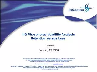
Iron loss • At a given frequency, the iron loss for electrical steel can be calculated from: Where Kh is the hysteresis coefficient Kc is the classical eddy coefficient Ke is the excess or anomalous eddy current coefficient. f is the frequency. Above coefficients can be calculated by the curvefitting of the manufacturer’s loss data sheet.
45W/lb Stator Material (Arnon 5) - Loss Core loss= 10.4 W
Core loss of a toroidal core inductor With 10% of 5th harmonics Without harmonics Same structure and same peak flux density as the stator.
Bearing Loss • Ball bearing loss • Loss is very high. • For bearing (0.1875 I.D. X .375 O.D. X .125 width ), each bearing loss is 50W @ 150 Krpm. • For the prototype, bearing loss will be about 200 W @ 200 Krpm. • Gas foil bearing • Low loss is realized. < 10 W
Windage Loss • Based on the equations that Krishna provided, the windage loss is 8.8 W. • Based on paper: M.N Awad, et.al, “Windage Loss Reduction Study for TFTR Pulse Generator”, 17th IEEE/NPSS Symposium , Vol.2 , pp. 1125-1128,1998. the calculated windage loss is 12.8 W.
Conclusion and Future Work • Future work • Stress analysis. (urgent) • If stress is OK, order Litz-wire and optimize structure.