Download

1 / 36
381 likes | 580 Views
GAS TURBINE POWER PLANTS. Gas turbines tend to be lighter and more compact than the vapour power plants. Gas turbines are used for stationary power generation.

E N D
Gas turbines tend to be lighter and more compact than the vapour power plants. • Gas turbines are used for stationary power generation. • In addition, the favourable power-output-to-weight ratio of gas turbines makes them well suited for transportation applications (aircraft propulsion, marine power plants, and so on).
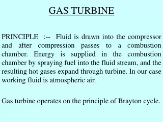
Simple gas turbine • Open to the atmosphere • Closed
The back work ratio for the cycle is • A relatively large portion of the work de-veloped by the turbine is required to drive the compressor. Typical back work ratios of gas turbines range from 40 to 80%. • In comparison, the back work ratios of vapour power plants are normally only 1 or 2%.
Ideal Air-Standard Brayton Cycle Air-standard ideal Brayton cycle
Thermal efficiency as a function of compressor pressure ratio for the cold air-standard ideal Brayton cycle, k = 1.4
Ideal Brayton cycles with different pressure ratios and the same turbine inlet temperatures
Example 1 Air enters the compressor of an ideal air-standard Brayton cycle at 100 kPa, 300 K, with a volumetric flow rate of 5 m3/s. The compressor pressure ratio is 10. The turbine, inlet temperature is 1400 K. Determine (a) the thermal efficiency of the cycle, (b) the back work ratio, (c) the net power developed, in kW.
Example 2 Determine the pressure ratio across the compressor of an ideal Brayton cycle for the maximum net work output per unit of mass flow if the state at the compressor inlet and the temperature at the turbine inlet are fixed. Use a cold air-standard analysis and ignore kinetic and potential energy effects.
Effects of irreversibilities on the simple closed-cycle gas turbine
Example 3 Reconsider Example 1, but include in the analysis that the turbine and compressor each have an efficiency of 80%. Determine for the modified cycle (a) the thermal efficiency of the cycle, (b) the back work ratio, (c) the net power developed, in kW.
Temperature distributions in counterflow heat exchangers (a) Actual (b) Reversible
Example 4 If a regenerator with an effectiveness of 80% is incorporated in the cycle of Example 1, determine the thermal efficiency.
Example 5 Consider a modification of the cycle of Example [1] involving reheat and regeneration. Air enters the compressor at 100 kPa, 300 K and is compressed to 1000 kPa. The temperature at the inlet to the first turbine stage is 1400 K. The expansion takes place isentropically in two stages, with reheat to 1400 K between the stages at a constant pressure of 300 kPa. A regenerator having an effectiveness of 100% is also incorporated in the cycle. Determine the thermal efficiency.
Internally reversible compression processes between two fixed pressures
Example 6 Air is compressed from 100 kPa, 300 K 1to 1000 kPa in a two-stage compressor with intercooling between stages. The intercooler pressure is 300 kPa. The air is cooled back to 300 K in the intercooler before entering the second compressor stage. Each compressor stage is isentropic. For steady-state operation and negligible changes in kinetic and potential energy from inlet to exit, determine (a) the temperature at the exit of the second compressor stage and (b) the total compressor work input per unit of mass flow. (c) Repeal for a single stage of compression from the given inlet slate to the final pressure.
Example 7 If the inlet state and the exit pressure are specified for a two-stage compressor operating at steady state, show that the minimum total work input is required when the pressure ratio is the same across each stage. Use a cold air-standard analysis assuming that each compression process is isentropic, there is no pressure drop through the intercooler, and the temperature at the inlet to each compressor stage is the same. Kinetic and potential energy effects can be ignored.
Example 8 A regenerative gas turbine with intercooling and reheat operates at steady state. Air enters the compressor at 100 kPa, 300 K with a mass flow rate of 5.807 kg/s. The pressure ratio across the two-stage compressor is 10. The pressure ratio across the two-stage turbine is also 10. The intercooler and reheater each operate at 300 kPa. At the inlets to the turbine stages, the temperature is 1400 K. The temperature at the inlet to the second compressor stage is 300 K. The efficiency of each compressor and turbine stage is 80%. The regenerator effectiveness is 80%. Determine (a) the thermal efficiency, (b) the back work ratio, (c) the net power developed, in kW.
Turbojet engine schematic and accompanying ideal T-s diagram
Other examples of aircraft engines (a) Turboprop (b) Turbofan (c) Ramjet
Example 9Air enters a turbojet engine at 0.8 bar, 240 K, and an inlet velocity of 1000 Km/h(278 m/s).The pressure ratio across the compressor is 8. The turbine inlet temperature is 1200 K and the pressure at the nozzle exit is 0.8 bar. The work developed by the turbine just equals the compressor work input. The diffuser, compressor, turbine, and nozzle processes are isentropic, and there is no pressure drop for flow through the combustor. For operation at steady state, determine the velocity at the nozzle exit and the pressure at each principal state. Neglect kinetic energy at the exit of all components except the nozzle and neglect potential energy throughout.